
Abstract
Content
- 1. Introduction
- 2. Causes of voltage unbalance
- 3. Effect of voltage unbalance. General remarks
- 4. Voltage unbalance coefficients for reverse and zero sequence
- 5. Synchronous machines. General remarks
- 6. Operation of synchronous generators under unbalanced loads
- 7. Control and analysis of power quality by voltage unbalance
- 8. Influence of voltage unbalance on the operation of electrical consumers and technological installations
- List of Sources
1. Introduction
Electromagnetic compatibility is the ability of technical means to function with a given quality in a certain electromagnetic environment without causing unacceptable interference to other TMs and without causing unacceptable electromagnetic effects on biological objects. Thus, electromagnetic compatibility characterises not only the interaction between electrical equipment and the electromagnetic environment, but also the interaction of technical means (TM) among themselves [1, 2].
Power quality (PQ) is a set of power properties that determine the compatibility of TMs included in the network. PQ characterises the measure of influence of power supply systems on electrical equipment of the network through conductive electromagnetic interference.
All available electromagnetic disturbances fall into two main categories: conductive and inductive disturbances. Conductive disturbances propagate in a conductive medium, such as the wires of an electrical network. Inductive or field disturbances propagate in the space surrounding the conductive medium. Sources of electromagnetic interference can be both technical means and natural phenomena.
From the point of view of the electric power industry, the more important issues are those related to the conductive type of interference. Power quality indicators (PQI) characterise the level of interference of this type.
2. Causes of voltage unbalance
Voltage unbalance results from the inclusion in the network of asymmetrical loads supplied from 1 or 2 phases of a three-phase network. Widespread examples of such unbalanced loads are welding equipment, induction furnaces, railway substations, power lines with unbalanced line phase impedance, household appliances, lighting, arc steel furnaces.
3. Effect of voltage unbalance. General remarks
Unbalance in three-phase networks leads to additional losses in their elements, reduces the service life of electrical equipment and reduces the economic performance of its operation, negatively affects the operation of AC electric machines.
Voltage unbalance in electric machines results in an additional magnetic field rotating in the opposite direction to the rotor's direction of rotation at twice the synchronous speed. This results in a braking torque and additional heating of the active parts of the machine due to currents of double frequency.
In some cases, voltage unbalance can be reduced by rational phase load distribution. The phase-by-phase redistribution of loads does not always allow voltage unbalance within the permissible limits. In this case, special symmetrical devices are used to reduce unbalance.
4. Voltage unbalance coefficients for reverse and zero sequence
An ideal symmetrical voltage system (Fig. 1,a) is characterised by the equality of phase (ОА, ОВ, ОС) and inter-phase (AC, CB, CA) voltages shifted relative to each other by the same angles of 120°. If these conditions are not met, the voltage is unbalanced (Fig. 1,b) [3, 4].
 and unbalanced (b) voltage systems")
Fig.1 Balanced (a) and unbalanced (b) voltage systems
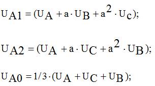
Voltage unbalance (currents) is characterised using the method of symmetrical components, according to which any asymmetrical three-phase system can be represented as three symmetrical ones forming forward, reverse and zero sequences:
Voltage unbalance is characterised by the reverse sequence voltage unbalance coefficients K2U and zero sequence voltage unbalance coefficients K0U . These coefficients have meaning only for three-phase networks and are calculated according to the following formulae:
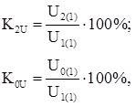
where U2(1) and U0(1) ‒ effective values of the main frequency of reverse and zero sequence, V; U1(1) ‒ is the effective value of the main frequency voltage of the direct sequence.
The value of K2U within the range of up to 2 % is normally acceptable at the terminals of any three-phase symmetrical power receiver (the limit value is 4 %). According to GOST 32144-13 [5], in distribution networks with single-phase lighting and household power receivers, the normally permissible value of K0U corresponds to 2 %, and the maximum permissible value is 4 %. The normally permissible value corresponds to a probability of 95% [6] of the time, and the maximum permissible value corresponds to 100% of the time.
5. Synchronous machines. General remarks
Synchronous machine (SM) is a collectorless alternating current machine (Fig.2), in which the rotor speed n1 is in strictly constant relation to the frequency f1 of the alternating current network (does not depend on the load) [7].

Fig.2 Synchronous generator TVV 800 MW
According to the type of rotor, synchronous machines are divided into machines with explicit poles and with implicit poles. Regardless of the type of SM, the stator of a SM consists of a housing and a core. The housings are cast from cast iron or steel. The stator core and winding are made in the same way as for asynchronous machines. The SM rotor is made of steel. The excitation winding on the rotor is made of copper wire. There are two ways of excitation: electromagnetic (independent and self-excitation) and permanent magnets. When the SM is excited by permanent magnets, there are no contact rings in the SM.
In modern brushless excitation systems, a synchronous generator is used as an exciter, where the armature winding is located on the rotor and the rectifier is mounted directly on the shaft. The starting or damping winding on the rotor is made in the form of rods, which in explicitly pole machines are placed in the grooves of pole lugs and connected at the end sides by plates.
6. Operation of synchronous generators under unbalanced loads
The stator winding of synchronous generators is usually connected in a star, with the neutral point in small machines isolated, and in large machines (Fig. 3) is earthed through a large resistance in order to fulfil the relay protection against earth faults. Therefore, zero sequence currents are either absent or very small [8].
Therefore, at unbalanced load of synchronous generators, apart from the direct sequence currents, there are practically only reverse sequence currents. The latter cause a number of undesirable phenomena in the machine and make the operating mode of the machine heavy.

Fig.3 Synchronous generator 1000 MW
Energy losses and rotor heating. Double frequency currents induced in the rotor by the reverse sequence stator magnetic field cause excessive losses in the rotor and its heating, as well as reducing the efficiency of the machine. The currents induced by the reverse field in the stilling windings of apparent pole machines and in the massive rotor of turbo generators can be very significant, and the active resistances to these currents under the influence of the surface effect will be large. Therefore, in case of significant load asymmetry, excessive and dangerous heating of stilling windings and solid rotors occurs.
The high rotor body temperature of the turbogenerator causes dangerous rotor deformations and the possibility of damage to the field winding insulation. The heating of the calming winding of an explicitly pole machine has little effect on the temperature of the field winding due to the distance of these windings from each other and better cooling conditions for the field winding of explicitly pole machines. The currents induced by the reverse field in the field winding are smaller due to the higher dissipation resistance of this winding. Therefore, the additional heating of the field winding under asymmetrical load is not high in solid pole machines.
Vibration. As a result of the interaction between the excitation flux and the stator reverse-sequence flux, as well as the stator direct-sequence field and the rotor double-frequency current field under asymmetrical loading, alternating torques and tangential forces pulsating at double frequency act on the rotor and stator.
In addition, due to the same causes, pulsating radial forces of attraction and repulsion between the poles of the stator and rotor fields arise, tending to deform the stator and rotor. These forces cause vibration of machine parts, noise and loosening of the stator core pressings. Pulsating forces of double frequency due to fatigue phenomena can also have a detrimental effect on the strength of welded joints, especially in the presence of welding defects. All of these factors are naturally stronger the greater the load unbalance.
Voltage symmetry distortion. Reverse sequence currents cause voltage drops in the phases of the stator winding whose vectors are orientated differently with respect to the forward sequence voltages in different phases. As a result, the generator voltage symmetry is distorted and the voltages of the more loaded phases will be lower. This worsens the operating conditions of receivers, especially asynchronous and synchronous motors.
In machines with stilling windings and massive rotors or poles, the reverse sequence resistance is smaller, so that the voltage symmetry distortion is also smaller. Physically, this is due to the fact that in such machines the stator reverse sequence flux is largely damped by the currents induced in the rotor and therefore this flux is induced in the winding phases.
7. Control and analysis of power quality by voltage unbalance
The main objectives of the PQ control are:
- Verification of compliance with the requirements of the standard in terms of operational control of PQI in general-purpose power grids;
- Verification of compliance of actual PQI values at the grid interface on the balance of ownership with the values fixed in the energy supply contract;
- Development of technical specifications for consumer connection in terms of PQ;
- Verification of fulfilment of contractual terms and conditions in terms of PQ with determination of permissible estimated and actual contributions of the consumer to PQ deterioration;
- Development of technical and organisational measures to ensure PQ;
- Determination of discounts (surcharges) to electricity tariffs for power quality;
- Electricity Certification;
- Finding the
causer
of PQ distortions.
Depending on the objectives being addressed in monitoring and analysing PQ, PQI measurements can take four forms:
- diagnostic control;
- inspection control;
- operational control;
- commercial accounting.
Diagnostic control of PQ - the main purpose of diagnostic control at the interface between the electric networks of the consumer and the energy supplying organisation is to detect the "culprit" of deterioration of PQ, determine the permissible contribution to the violation of the standard requirements for each PQ, include them in the energy supply contract, and normalise PQ.
Diagnostic control should be carried out when issuing and verifying compliance with technical conditions for connection of a consumer to the power grid, when controlling contractual conditions for power supply, as well as in cases when it is necessary to determine the share contribution to the deterioration of the PQ of a group of consumers connected to a common supply centre. Diagnostic control should be periodic and provide for short-term (not more than one week) measurements of PQI. During diagnostic control, both standardised and non-standardised PQI are measured, as well as currents and their harmonic and symmetrical components and their corresponding power flows.
If the results of the diagnostic control of the power quality confirm that the consumer is "guilty" of violating the power quality factor standards, the main task of the energy supplying organisation together with the consumer is to develop and assess the possibilities and timing of measures to normalise the power quality factor. For the period until these measures are implemented, operational control and commercial metering of power quality should be applied at the interface between the power grids of the consumer and the energy supplying organisation.
At the next stages of diagnostic PQ measurements, the control points should be the busbars of the district substations, to which the cable lines of consumers are connected. These points are also of interest for controlling the correct operation of transformer tap changers, for collecting statistics and recording voltage sags and temporary overvoltages in the electrical network. In this way, the operation of already existing QE facilities is monitored: synchronous compensators, batteries of static capacitors and transformers with on-load tap-changers providing the specified voltage deviation ranges, as well as the operation of protection and automation equipment in the electrical network.
Inspection control of electric power plants is carried out by certification bodies to obtain information on the condition of certified electric power in the power supplying organisation's grids, on compliance with the conditions and rules of certificate application, in order to confirm that electric power plants continue to comply with the established requirements during the period of certificate validity.
Operational control of PQ is necessary in operating conditions at points of the electric network where voltage distortions exist and cannot be eliminated in the near future. Operational control is necessary at connection points of traction substations of railway and urban electrified transport, substations of enterprises having power supply units with non-linear characteristics. The results of operational control should be received via communication channels to the dispatching points of the power supplying organisation's electrical network and the industrial enterprise's power supply system.
Commercial metering of PQI should be carried out at the interface between the electric networks of the consumer and the energy supplying organisation, and its results are used to determine discounts (surcharges) to electricity tariffs for its quality.
Commercial metering of PQ should be carried out continuously at metering points of electricity consumption as a means of economic impact on the perpetrator of PQ deterioration. For this purpose, devices combining the functions of power metering and power quality measurement should be used. Availability of electricity metering and PCE control functions in one device will allow combining operational control and commercial metering of electric power quality, and common communication channels and means of processing, displaying and documenting information of the ASCME can be used. [9].
8. Influence of voltage unbalance on the operation of electrical consumers and technological installations
Voltage unbalance in the electrical networks of enterprises is caused by the presence of powerful single-phase loads (induction melting and heating furnaces, welding units, electroslag melting furnaces), as well as three-phase loads operating in asymmetrical mode for a long time. The three-phase voltage system may be unbalanced when the plant network is supplied from an AC traction substation.
Voltage unbalance in three-phase networks results in additional losses in power grid elements, reduces the service life of lamps and electrical equipment and reduces the economic performance of its operation [10].
Voltage unbalance in AC electric machines results in magnetic fields rotating not only with synchronous speed in the rotor rotation direction, but also with double synchronous speed in the opposite direction. This results in a braking electromagnetic torque as well as additional heating of the active parts of the machine, mainly the rotor, due to currents of double frequency.
In motor drives with reverse sequence voltage coefficients less than 5-6%, the reduction of the motor torque is negligible. The influence of asymmetry on losses in the electric motor and, consequently, heating and shortening the service life of its insulation is more pronounced.
When operating the motor with rated torque and voltage reverse sequence coefficient equal to 4 %, its insulation life is reduced by about 2 times only due to additional heating (Fig.4). If the voltage on one of the phases is significantly higher than the nominal value, the reduction in insulation life will be even greater. In order to ensure normal operating conditions of electric motors in this case it is necessary to reduce their available power, and when designing - to increase the rated power of electric motors, unless special measures are provided for symmetry of network voltages. These circumstances arise, for example, in the design of electrified railway transport at mining and some other industrial enterprises.
")
Fig.4 Additional losses and lifetime reduction for induction motor under voltage unbalance (animation: 12 frames; 49,5 Kb)
Voltage unbalance in synchronous motors can cause dangerous vibrations in addition to additional losses and heating of the stator and rotor due to alternating torques and tangential forces pulsating at twice the mains frequency. If the asymmetry is significant, vibration can be dangerous, especially if the welded joints are not strong enough or have defects. If the current asymmetry does not exceed 30 %, dangerous overvoltages do not usually occur in structural elements.
Additional power losses in the synchronous motor under unbalanced load cause local heating of the field winding, which leads to the need to reduce the field current and thus reduce the value of reactive power delivered to the network. It may be necessary to reduce the generator active load or the torque on the synchronous motor shaft.
According to the "Rules of Technical Operation of Electric Power Stations and Networks", long-term operation of turbine generators and synchronous compensators is allowed for a stator phase current difference not exceeding 10% of the nominal value, provided that none of the phase currents exceeds the nominal value. Under the same conditions, for hydro generators the current difference is allowed up to 20 %.
List of sources
- Тимиргазин Р.Ф. Электромагнитная совместимость : учебное пособие / Тимиргазин Р.Ф.. — Ульяновск : Ульяновский государственный технический университет, 2017. — 48 c. — ISBN 978-5-9795-1649-3.
- Овсянников, А. Г. Электромагнитная совместимость в электроэнергетике : учебник / А. Г. Овсянников, Р. К. Борисов. — Новосибирск : Новосибирский государственный технический университет, 2017. — 194 c. — ISBN 978-5-7782-3367-6.
- Савина Н.В. Качество электроэнергии : учебное пособие / Савина Н.В.. — Благовещенск : Амурский государственный университет, 2014. — 182 c.
- Кобозев В.А. Качество электроэнергии и энергоэффективность систем электроснабжения потребителей : учебное пособие / Кобозев В.А., Лыгин И.В. — Москва, Вологда : Инфра-Инженерия, 2022. — 356 c. — ISBN 978-5-9729-0770-0
- ГОСТ 32144-2013. Электрическая энергия. Совместимость технических средств электромагнитная. Нормы качества электрической энергии в системах электроснабжения общего назначения. Введ. с 01.07.2014.
- Аркашов, Н. С. Теория вероятностей и случайные процессы : учебное пособие / Н. С. Аркашов, А. П. Ковалевский. — 2-е изд. — Новосибирск : Новосибирский государственный технический университет, 2017. — 238 c. — ISBN 978-5-7782-3375-1
- Дробов А.В. Электрические машины : учебное пособие / Дробов А.В., Галушко В.Н.. — Минск : Республиканский институт профессионального образования (РИПО), 2015. — 292 c. — ISBN 978-985-503-540-5.
- Угольников А.В. Электрические машины : учебное пособие / Угольников А.В.. — Саратов : Ай Пи Ар Медиа, 2019. — 157 c. — ISBN 978-5-4497-0020-9.
- Лыкин А.В. Учет и контроль электроэнергии. Конспект лекций : учебное пособие / Лыкин А.В.. — Новосибирск : Новосибирский государственный технический университет, 2019. — 171 c. — ISBN 978-5-7782-3797-1
- Железко Ю.С. Потери электроэнергии. Реактивная мощность. Качество электроэнергии : руководство для практических расчетов / Железко Ю.С.. — Москва : ЭНАС, 2016. — 456 c. — ISBN 978-5-93196-958-9.