
Abstract
This abstract is used as an example, with the permission of Evgeniy Tatolov.
Original: http://masters.donntu.ru/2011/fknt/tatolov/diss/indexe.htm
Table of contents
- Introduction
- 1. Relevance of the topic <
- 2. The purpose and objectives of the study, the planned results
- 3. Hydraulic pulsator
- 3.1 Principle of operation of the Hydraulic Pulsator
- 4. Necessary modernization of the water supply system of blast furnace cooling plates.
- Conclusions
- List of sources
Introduction
The development of hydraulic pulse equipment is inextricably linked with the need to automate the necessary calculations. To do this, we have studied the proposed model. Taken from the PhD dissertation: "mathematical modeling hydraulic shocks in branched pipeline systems", by the authorship of Candidate of Physical and Mathematical Sciences Lyudmila A. Buraeva Her work allows us to study the phenomenon of water hammer in closed branched pipelines, which is directly related to the topic master's thesis, the purpose of which is to improve the quality of cleaning measures for blast furnace refrigerating stoves and as a result, an increase in service life, which leads to a reduction in maintenance costs.
Let's consider the phenomenon of water hammer itself. Hydraulic shock is not a stationary phenomenon, caused by a rupture of the liquid and characterized by a wave of increased pressure. Usually, a water hammer is considered as a negative phenomenon, which entails the destruction of the hydraulic system in which it occurred. In our work, based on the installation created in DonNTU (hydraulic pulsator), it is planned to create a system designed for cleaning pipes from potassium-magnesium deposits, leading to a deterioration in the thermal conductivity of refrigerating stoves.
1. The relevance of the topic
Against the background of the dynamics of industrial production cuts in Russia and the negative dynamics of prices for blast furnace products, reducing long-term costs will have a positive impact on the functioning of current capacities. Otherwise, the expected reduction is the production will decommission many blast furnaces, which will lead to inappropriate spending in the future, when the dynamics of the market it will change to the opposite.
Our proposed method will reduce maintenance costs in the long term. By extending the service life of blast furnace cooling plates, otherwise requiring regular replacement. The relevance of this topic is also due to the possibility of adapting the resulting system to other industries and the general development of hydro-pulse technology has the ability to be used in various fields, including household.
2. The purpose and objectives of the study, the planned results
The purpose of the work is to increase the efficiency of maintaining the initial parameters of blast furnace refrigerating plates. To increase the service life and obtain a long-term economic effect.
Work tasks.:
- Investigation of current cleaning methods and their evaluation.
- Description and evaluation of the new cleaning method.
- Formulation of a mathematical model.
- Assessment of the quality of the new calculation approach, formulation of recommendations.
The object of the study: a pulsating jet as a tool to improve the removal of carbonate deposits from the walls of coils..
The subject of the study: a method for automating the necessary calculations to update the work to meet current capabilities and requirements.
As part of the master's work, it is planned to obtain relevant knowledge on the following issues.
- Obtaining software to simplify settlement activities.
- Determining the applicability of this approach to real-world tasks.
- The possibilities of modifying current systems to meet the needs of a new cleaning method refrigerator stoves.
- The possibility of an accurate assessment of the results obtained.
In the experimental part of the master 's thesis, it is planned to build a full-size operating installation for obtaining experimental the data and their relationship to the data obtained theoretically. To evaluate the software calculation method as valid.
3. Hydraulic pulsator
A hydraulic pulsator is an assembly for creating continuous non-stationary liquid jets and controlling them to ensure the destruction of coal, G. P. Is used independently or how it will be executed. horn organ. combine harvesters
3.1 Principle of operation of the Hydraulic Pulsator
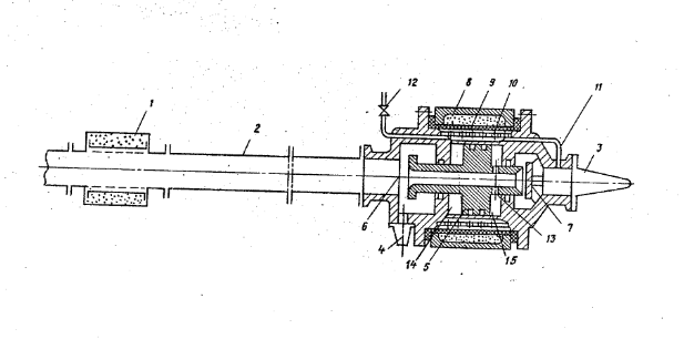
Figure 3.1 – Hydraulic pulsator circuit
The hydraulic pulsator works as follows. When the control valve and is open, the water flowing through the transfer tube 10 from the main pipeline 9 into the diaphragm space of the air cavity 8 flows freely into the atmosphere. This leads to a pressure in the piston cavity from the seat side 5 (cavity A) it remains close to atmospheric. Therefore, when water enters from the main pipeline 9 into the inner cavity of the piston valve 4 and the pressure in the piston cavity from the seat side 6 (cavity B) becomes equal to the input, the latter moves to the leftmost position all the way to the saddle 5. As a result, the water, passing through the oscillator, fills the shock the pipeline 3 and flows through the working nozzle 12. After that, a control valve is needed 11 close, which will lead to an increase in pressure in the cavity A to the supplied one. Pressure equality in in the cavities A and B of the piston valve 4, it moves to the rightmost position until it stops at the seat of the high side 6. Water access from the pipeline 2 to the discharge nozzle opens 7 and the access of water to the pipeline stops 3. Water is dispersed in the shock pipeline 2 to the maximum possible speed.
The hydraulic pulsator is put into self-oscillation mode after the pressure in the cavity is reduced A to a value less than the pressure in the cavity B by opening the control valve 11. In the future, the pressure in the cavity A remains constant and is smaller in magnitude than the supplied one (in the main pipeline 9). As soon as the pressure in cavity A becomes lower than in cavity B, The piston valve 4 will move to the leftmost position. Water access to the discharge nozzle 7 and both shock pipelines is closed they communicate with each other. A high phase of flow fluctuations begins in the impact pipeline 2. Entering the impact pipeline 3 of a smaller cross section, the water flow has a high velocity along compared with the speed of the water flow passing through the impact pipeline 2 at this time, since the cross section of the latter is larger. Thus, through both shock pipelines from the generator vibrations propagate shock waves of increased to the same pressure, but different speeds, and the speed in pipeline 3 is greater than in pipeline 2. When the shock wave, propagating through the pipeline 3, reaches the working nozzle 12, the flow rate decreases , because the resistance of the nozzle is greater than the resistance of the pipeline 3. As a result, the pressure increases again, and the wave of this secondarily increased the pressure spreads from the working nozzle 12 to the oscillator. At the same time a wave propagates through the shock pipeline 2 towards the hydropneumoaccumulator 1 pre-increased pressure, which is reflected from the last wave of the supplied pressure. When the wave reflected from the hydropneumoaccumulator 1 approaches the oscillator, the pressure at the latter decreases and becomes less than the pressure in the cavity A of the piston valve. As a result of the pressure difference in cavities A and B, the piston valve 4 moves to the far right position. The access of water from pipeline 2 to pipeline 3 is stopped, and the discharge nozzle 7 It opens. The high phase of pressure fluctuations in the impact pipeline 2 ends and the low phase begins. The first wave of low pressure spreads to the hydropneumoaccumulator 1. After this wave is reflected from the hydropneumoaccumulator and approaches the oscillator , the pressure in front of the discharge nozzle 7, in the cavity B increases slightly, remaining, however, it is less than the constant pressure in the cavity A of the piston-valve 4. Therefore the discharge nozzle 7 remains open and spreads through the impact pipeline 2 the next wave of low pressure, etc., When the hydraulic pulsator is operating in the ram In this mode, the number of pressure waves traveling through the shock pipeline 2, both ways in the low phase is usually 3-5 and depends on the magnitude of the constant pressure in the cavity And the piston is the valve 4. The closure of the discharge nozzle 7 and the end of the low phase of pressure fluctuations water in the shock pipeline 2 occurs when the pressure in front of the discharge nozzle 7 and in the cavity B of the piston valve 4, increasing abruptly with each arrival of the wave reflected from the hydropneumoaccumulator 1, does not become greater than in the cavity A. During the low phase in pipeline 2, it is not hydraulically connected to pipeline 3. Therefore, flow fluctuations in both pipelines do not affect each other.
4. The necessary modernization of the water supply system of blast furnace cooling plates.
To connect the installation, it is necessary to modernize the water supply system in order to include a hydraulic pulsator in the system. Replacement of the power plant is not required, it is enough to upgrade the pipeline.
Let's consider the schematic diagram of the system for connecting refrigerating stoves (Fig. 4.1).
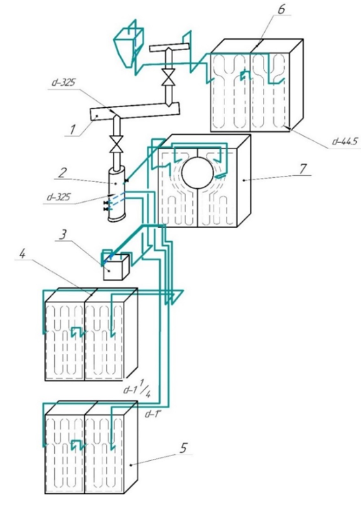
1 – annular pipeline; 2 - pressure manifold; 3 - drain tank; 4 – refrigerating plates of the upper bream; 5 – refrigerating plates of the lower leshchadi; 6 - refrigerating plates of the shoulder pads; – refrigerator plates of the tuyere zone.
Figure 4.1 is a diagram of the cooling communication of the lower zone of refrigerators. Cooling of shoulder pads, tuyere zone and bream.
Thus, you can determine that there are two connection options, one is a connection to an annular pipeline, the second option is to connect to a pressure manifold. Both options have a number of advantages and disadvantages.
In the first case, the system can be mounted until the end of its service life. Easy installation and operation. The disadvantages include hydraulic losses, and as a result, energy overruns.
In the second case, the advantages include mobility, the area of application and the ability to reduce installation dimensions and input power requirements. The disadvantages here include: the need to install all collectors, which are to be replaced with a new type (Figure 4.2).
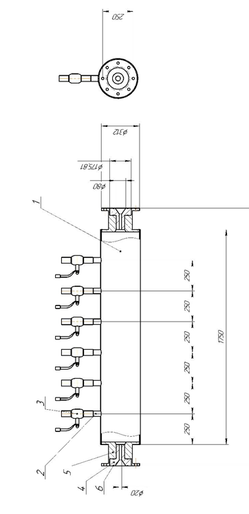
1 Pipe 325*6; 2 Pipe 44*6; 3 Ball valve; 4. Nozzle; 5 Transition flange; 6 Ring 112-118-25-2-4
Figure 4.2 – Modified pressure manifold. Cooling of shoulder pads, tuyere zone and bream.
Conclusions
This work is aimed at solving the scientific and technical task of modernizing the system cleaning of blast furnace refrigerators and in the installation of rational parameters of a device that creates a pulsating jet ensuring the efficiency of the cleaning process of refrigerating plates, this prevents the harmful effect of high temperatures on the refractory masonry of the blast furnace.
The use of the proposed method will lead to an increase in the service life cooling systems and blast furnaces in general.
The main conclusions, scientific and practical results of the work:
- Assessment of the capabilities of hydraulic pulsators
- Determining the applicability of this approach to real-world tasks.
- The possibility of modifying current systems to meet the needs of a new cleaning method refrigerator stoves.
When writing this paper, the master's thesis has not yet been completed. The full text of the work and materials on the topic can be obtained from the author or his supervisor.
List of sources
- Zhukovsky, Nikolai (1900), "Uber den hydraulischen Stoss in Wasserleitungsrohren" [On hydraulic shock in water pipes], Memoirs of the Imperial Academy of Sciences of St. Petersburg, 8th series (in German), 9 (5):1-71
- Arbatov A. Mineral resource base of the country//Economist. - 2000. - No.2
- Regional economics: Textbook for universities/ T.G. Morozova, M.P. Pobedina, G.B. Polyak, etc.; Edited by prof. T.G. Morozova. - 2nd ed., reprint. and additional - M.: UNITY, 2001
- The Russian Statistical Yearbook. 2007/Statistical collection/Rosstat. - M., 2007
- Economic Geography of Russia: A textbook for university students studying economics and management/Edited by T.G. Morozova. - 3rd edition. - Moscow: UNITY-DANA, 2007
- Water management of ferrous metallurgy plants: Sernikov N.F., Krasavtsev G.N., Ilyechiv Yu.I., Rylov A.V., M., "Metallurgy", 1973, 408 p .
- TI D-01-2017. Production of cast iron.
- PT 1-12-2021. Operation of blast furnace cooling systems.
- Equipment of blast furnace shops [Text]: textbook. manual / P.F. Gakhov, A.A. Kharitonenko. Lipetsk: Publishing house of Lipetsk State Technical University. 2014. – 132 p.
- UDC 669.162.21/ V.K. Kropotov, V.G. Druzhkov, I.E. Prokhorov Blast furnace design: Textbook. Fig. 37. Table 12. Bibliogr. 90 titles.
- NPAOT 27.1-1.02-20 . "Safety rules in blast furnace production"
- IOT 01/02-2021. "Labor protection instructions for the plumber of the blast furnace of the blast furnace shop"
- NPAOT 0.00-4.15-19 . "Standard regulation on the occupational safety management system"
- GOST 8734-75 "Seamless cold-formed steel pipes"
- Adamov V.G. Creation and selection of rational parameters of pulsed hydraulic monitors with a shock pipeline: Dis. cand. tech. Sciences.: 05.05.06. – Donetsk, 1989. – 273 p.
- GOST 5264-80 "Manual arc welding. The joints are welded. Main types, structural elements and dimensions"
- LABOR PROTECTION LAW OF the Russian Federation
- Hydraulic pulse devices/ V.S. Kolomiets, N.S. Surgai, M.P. Sorokopud, A.L. Zuikov, V.E. Lagoda / Patent for utility model No.21305. Ukraine, 2007.
- Geyer V. G., Dulin V. S., Zarya A. N. Hydraulics and hydraulic drive: Textbook. For universities. – 3rd ed., revised. and additional – M. : Nedra, 1991. – 331 p.