
Abstract
Table of contents
- Introduction
- 1. The relevance of the topic
- 2. The purpose and objectives of the study, the planned results
- 3. Turning and screw-cutting machine TV-16
- 3.1 General view of the machine
- 4.Modernization of the system.
- Conclusions
- List of sources
Introduction
Despite the rapid development in the past, at the moment the industry in Donbass is not experiencing its best times. The rapid development of industry in the past has brought development in all areas to this region. In addition to the main areas of coal mining, metallurgy and mechanical engineering, the development of all contributing industries began here, which allowed Donbass to develop so quickly in the shortest possible time. But the recent events caused by the fighting have caused great damage, both to the heavy industry and to the development of the region as a whole.
After the end of hostilities, the Lugansk and Donetsk People's Republics will need to restore industry in these territories as soon as possible, in order to increase economic indicators, increase the number of jobs and, as a rule, increase demographic indicators. Despite the outdated technologies of heavy industries, they are key for this region and their restoration will be a top priority.
For the training of specialists for mechanical engineering in educational institutions of the republic, light turning and screw-cutting machines TV-16 can be used. These machines are great for small jobs related to drilling, threading, boring and other simple types of turning work.
1. The relevance of the topic
Against the background of the dynamics of small industrial production in Donbas and a small number of jobs, it has a detrimental effect on industry and demographics in the region. Otherwise, a small number of jobs may cause the departure of the indigenous population to other regions, which will adversely affect the development of the region as a whole
The proposed method will not only increase the efficiency of the bottom machine, maintenance costs in the long term, but will also lead to an increase in jobs and attract new specialists to the region.
2. The purpose and objectives of the study, the planned results
The purpose of the work is to modernize the TV-16 machine by replacing the asynchronous motor in the design with a stepper motor, this will allow you to control the processing of blanks using a control program recorded on a personal computer.
Tasks of the work:
- Description and evaluation of the new machine.
- Formulation of a mathematical model.
- Assessment of the quality of the new calculation approach, formulation of recommendations.
The object of the study: the efficiency of the machine when replacing the standard motor with an asynchronous one.
The subject of the study: software setup and adjustment to update the work to meet current requirements.
As part of the master's work, it is planned to obtain relevant knowledge on the following issues.
- Development of a program for smooth adjustment of the speed on the spindle
- The possibility of modifying current systems to meet the needs of various enterprises
- The possibility of an accurate assessment of the results obtained.
3. Turning and screw-cutting machine TV-16
The TV-16 turning and screw-cutting machine is a small-sized machine designed for processing metal parts. The main task of this machine is to perform elementary turning operations. Despite the simplified assembly mechanism of the machine, there is no running shaft, gearboxes, the device can perform various types of metal turning with an average complexity of operations
3.1 General view of the machine
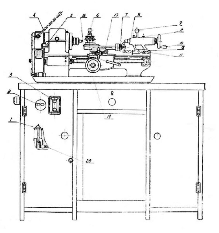
Figure 3.1 – Diagram of the TV-16 machine
1. Belt tension and release handle to switch the spindle rotation speed. 2. The input switch. 3. Push-button station. 4. Handle for clamping the bar with a collet clamp. 5. Trenzel handle for changing the feed direction. 6. A handle for fixing the tool holder. 7. Handle for turning on the masterbatch nut. 8. Handles for moving the upper slide. 9. Handle for fixing the tailstock pinole. 10. Handwheel for moving the tailstock pinole. 11. Screw for transverse displacement of the tailstock. 12. A handle for fixing the tailstock on the frame. 13. A handle for fixing the caliper on the bed. 14. Handle for moving the cross slide. 15. Handwheel for longitudinal movement of the caliper. 16. Screws for adjusting the gap in the guides of the upper slide. 17. Screws for adjusting the gap in the direction of the cross slide. 18. Screws for fixing the housing to the tailstock plate. 19. Screws for adjusting the gap in h
The push-button station and the spindle speed switch are located on the front surface of the table, the rest is directly on the aggregate itself
The spindle headstock. The headstock consists of a housing, a metal bit and a shaft with a three-stage pulley. The main task is the rotation of the working cardan connected to a radial thrust bearing mounted in front of the shaft. There is also a pulley on the main shaft, which provides a set rotation speed by an electric motor. For the reverse rotation of the shaft, a trenzel is provided in the machine. Two cone-shaped bearings hold the spindle and pulley. By changing the location of the bearing with the help of a nut, the gap between it and the spindle assembly is adjusted.
A gearshift and feed device. There is no gearshift and feed box in the TV-16. The spindle speed is regulated by changing the belts between the gaps of the pulleys, thus obtaining one of 6 modes. By changing the gears in the guitar, they control the pitch of the thread being cut or the feed speed. The gear assembly is located in a closed box, on the door of which there is a switch that stops, for safety reasons, the operation of the equipment in case the door is opened during the working process.
The apron is designed for the movement of the caliper stroke and is controlled by a handle on the body. The carriage is attached to the device's apron with special screws. The detachable nut located in the apron is driven by the handle. When the nut is turned on, the tool holder is supplied by the lead screw. When turned off, it is performed manually by rotating the flywheel.
The caliper. The main task of the stupor is to fix and move the cutting tools in the inclined, transverse and longitudinal directions. The assembly includes a carriage, a tool holder and a slide. The movement of the carriage is set by guides along the frame, all the components of the caliper are installed on it. The lead screw and pinions with a rail ensure the longitudinal movement of the caliper.
The tailstock. To fix and correctly position long parts, a tailstock with hexagonal guides is provided on the machine. Performs the role of an additional support, fixed with a grooved bolt.
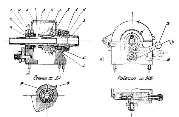
Figure 3.2 - Headstock of the TV-16 lathe
The headstock (Fig. 3.2) consists of a housing — 1 with a lid — 2, a spindle - 3 and a trenzel - 20 for reversing the feed using a handle - 19, The spindle with a pulley — 4 mounted on it is mounted on two sliding bearings - front - 9 and rear - 12. Plain bearings are inserts (bushings) with a conical outer surface. The inserts are incised along three formers and cut along the fourth. The gap between the spindle and the liner is regulated by the axial movement of the latter in the housing using a front nut 5 with a felt seal — 15 and a rear nut - 7. When tightening nuts 5 and 7, the inserts are compressed with some distortion of the inner surface of it. To eliminate this distortion, screws — 13 are provided, which have wedge-shaped heads - 14 inserted into the inclined slots of the inserts. When adjusting, the head 14 bursts the liner tightly pressing it against the conical surface of the housing (or to the sleeve - 11 of the rear bearing). The pulley mounted on the spindle — 4 is attached to the
4.Modernization of the system.
To connect the new motor, an improved torque transmission scheme was developed from the motor to the machine spindle
Connection diagram
Figure 4.1 – Motor connection diagram.
Thus, with our modernization, we significantly simplify the machine design, we can not only switch between spindle speeds more quickly and clearly, but also remove unnecessary belt drives and gearbox, which allows us to free up extra space under the machine and makes our design easier.
Conclusions
This work is aimed at solving the problem of modernizing the machine, replacing the old engine with a new asynchronous one will not only reduce the cost of the machine and it will make working on it more comfortable, but also reduce the payback time of the machine
List of sources
- Passport and manual for the desktop turning and screw-cutting machine model TV-16 – Kaz. SSR Alma-Ata State Farm, plant named after S.M.Kirov.
- Acherkan N.S. Metal-cutting machines, Volume 1, 1965
- Encyclopedia T4-7 Metal–cutting machines - 2002, editor-compiler B.I.Cherpakov
- Chernykh, I. V. Modeling of electrical devices in MATLAB. SimPowerSystems and Simulink / I. V. Chernykh. – M. : DMK Press, 2007. – 288 p.
- Push, V. E. Small movements in machine tools. – Leningrad: Gosgortehizdatat, 1961. – 124s.
- Petrakov Yu.V. automatic control of processes of processing materials by cutting: a textbook. Kiev: Ukrniiat publ., 2004, 383 p. (in Russian).
- Batov V.P. Lathes, 1978
- Beletsky D.G. Handbook of a universal turner, 1987
- Skhirtladze A.G., Novikov V.Yu. Technological equipment of machine-building industries, 1980