Автор: Al. Armii Krajowej
Источник: 1Czestochowa University of Technology, Institute of Mechanical Technologies, Al. Armii Krajowej
21, 42-201 Czestochowa, Poland
Abstract. CNC machine tools are currently predominating in the machine-building industry. Generally, these machine tools are equipped with control systems supplied by the world's leading manufacturers, such as Siemens, Fanuc or HeidenHein, and are very expensive. In parallel, many cheap amateur and semi-professional CNC machine tool solutions are being developed. Below, a CNC milling machine of welded construction is described, which is intended to be, at the same time, a test stand. The design of the milling machine is based on steel closed sections of a large cross-section and a big wall thickness. This has allowed a rigid frame structure to be obtained. To obtain high displacement accuracy, high-accuracy profiled rail slideways have been used, along which prestressed linear ball bearings move. The machine tool has been furnished with a fourth numerically controlled axis, which is demountable.
Keywords: machine tools, mach3, welded frame
Aside from professional CNC machine tools used in many branches of industry [1, 2], the market of amateur solutions of such machine tools is intensively developing. For amateur CNC machine tools, their main distinguishing feature is a low manufacturing cost.
Most often, these are 3-axis machine tools of a bolted construction based on aluminium section bars (Figure 1), or even wooden section bars, sometimes of large overall dimensions. It is, therefore, hard to expect rigidity and accuracy from such solutions. A control system commonly used in such machine tools is Mach3 which, in spite of its high capabilities, is very cheap.
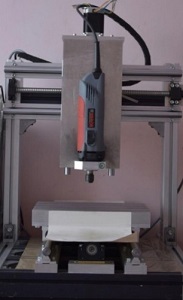
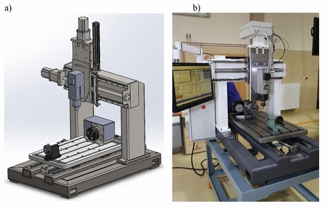
Shown below is the authors' design of a 4-axis welded-construction CNC milling machine with enhanced rigidity and machining accuracy, which is intended to be, at the same time, a test stand [4].
The worm described in the article was made on this milling machine [5]. The machine was successfully used to shape the helical surface of the worm with an arbitrary axial profile and the required accuracy of mating area with the worm wheel [6, 7], and spur gears with tooth line modification [8] machined by Step by Step method.
In view of its low cost, the Mach3 program has been used for control, which is the most common CNC machine control software program, both for commercial and non commercial applications [9, 10]. It controls the operation of stepper motors or servo-drives. Thanks to its capability to simulate a PLC controller and ModBus communication, Mach3 offers the possibility of transforming a PC into the controller of practically any machine. The program controls the machine operation based on G-codes (up to 10,000,000 lines), which can be prepared from vector files using, e.g., the LazyCam program. The program can control any set of a controller and a stepper motor. Also, any mechanical solution of drive transmission can be used (e.g. screws, toothed bars or toothed belts) – the program is able to define the work parameters of each axis separately. There is the capability to control up to 6 axis and to use macros written in VBscript. The program's window offers the preview of the tool path and the ongoing monitoring of machining parameters, such as feed rate or spindle rotational speed.
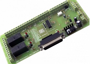
Machine tools of this type commonly utilize the SSK-MB1/2 controller – Figure 2 [11]. The SSK-MB2 main board is designed for connecting up to 4 stepper motor (servo) controllers to a PC furnished with the LPT parallel port. All devices (controllers, limit switches, the spindle) are hooked up independently to respective port pins. There may also be controller versions that communicate with the computer using the USB port, Ethernet, or based on a PLC controller.
In the machine tool under discussion, the more expensive SmoothStepper controller is implemented [12], which is a 6-axis motion controller that communicates with the computer via the Ethernet port – Figure 3.
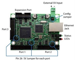
Based on received control signals, Mach 3 generates a high-quality high-frequency rectangular waveform for the stepper motors and the servo-drives. By cooperating with Mach3, a controller connected to the computer's Ethernet port can substitute for even three LPT ports of the computer. This allows computers that are not furnished with the LPT port as standard to control the machine's operation using the Mach3 program.
For the configuration and control of the controller's operation, two windows [9, 13] are used, which can be found in the Plugin Control main menu of Mach3.
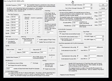
The first of them, Figure 4, enables the configuration of the communication of the SmoothStepper controller with the Mach3 program. This includes the capability to define:
– the frequency, at which the updating of transmitted data (Controller Frequency) is to take place, that is how many times per second the motor speed should be refreshed during the controller's operation. The higher the refresh rate, the "smother" the motor run should be. However, increasing this value will also bring about adverse effects, such as a reduction of the data buffer (each time the frequency is doubled, the buffer capacity will decrease by half). A higher refresh rate cause also a greater load of the Ethernet connection between the controller and the computer.
– the maximum frequency of control pulses for individual axes (Max Step Frequency). Set the nearest frequency higher than the frequency required for a given axis (depending on the expected speed and the number of motor steps, while allowing for the controller's microstep, or the number of servo-drive encoder pulses). If in doubt as to which frequency to select, 4MHz can be set. The motor run might not be "smooth" at that case, but the controller's counters should not become overfilled.
– the spindle control method (Spindle). One of the three control modes can be selected: On/Off, PWM signal, and the step and the direction.
The orientation of pins from 2 to 9 of Port 2 can also be defined (thus obtaining more inputs). PlugIn offers also the capability to define a kind of a software filter for individual input signals (Noise Filtering ). The purpose of this is to eliminate the noise.
If changes in the setting of maximum frequencies for individual axes have been made, then readjust the motors (Motor Tuning) and restart the program for the new settings to take effect.
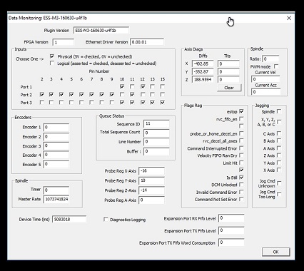
The second configuration window, Data Monitoring, is used for "previewing" the exchange of information between the controller and Mach3 (Mach4) – Figure 5.
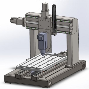
The whole machine tool construction is based on large cross-section thick-walled closed section bars of enhanced-strength steel S355J2 – Figure 6. The construction was welded by the MAG method using the following welding parameters: current intensity – welding currents, 270-280 A; voltage, 26 V; and 1.2 mm-diameter wire in grade G4Si1. Then, it was subjected to the process of vibration stabilization employed as a technology that substitutes for stress relief annealing. The vibration technology provides dimensional stability similar to the stability obtained during natural ageing [14]. This has allowed a rigid frame structure to be obtained [1].
To obtain high displacement accuracy, high-accuracy profiled rail slideways were used, along which high load-capacity linear ball bearings pre-stressed with 0.03-0.05 Cdynes i.e. 620N/m to move. For each axis, four linear bearings are used, each of a static load capacity of C0 = 69160N. The allowable deviation in absolute dimension among several carriages which are all assigned to a single rail or divided into a pair of rails amounts to 0.015mm.
Individual supports for the X, Y, Z axes, as well as, optionally, for the A or B axis, are driven by stepper motors with a holding moment of 8.5 Nm through vibration-reducing clearance-free claw couplings mounted axially with a ball screw via a flexible connecting link. Linear displacements are effected by a roller screw gear with a spiral lead of 5 mm. The ball screw is executed in accuracy class 5. The maximum spiral lead error equals 0.018 mm.
Each screw is paired with a prestressed nut (with a prestress torque of 0.07 Cdynes) to remove the reversal backlash.
The milling machine is optionally furnished with a fourth axis – rotary, numerically controlled A or B, depending on the manner in which it is mounted on the machine tool table – Figure 7. The drive of this axis is also effected by a stepper motor through a toothed belt transmission with a transmission ratio of 1:1.8 and onto a spindle ended with a self centring chuck. For machining rolls of a length exceeding the diameter, a tailstock with a dead centre is used for supporting on the other side.
In addition, the milling machine's spindle is capable of being set at an angle within a narrow range of ±10 degrees.
A 5.5 kW electric spindle of a maximum rotational speed of 18 000 rpm and with an ER32 tip for fixing tools with a cylindrical grip is used as the main drive of the milling machine. The rotations of the electric spindle are regulated by a Simens Sinamics V20 inverter.
For unloading the spindle frame, a pneumatic servomotor with a brake is employed. The brake activates when there is no pressure and blocks the movement of the servomotor piston rod, thereby holding the spindle support at the current level (the spindle does not fall down).
The working space in individual axes, x/y/z, is 450/720/320 mm, respectively.
This is a 4-axis CNC milling machine with sufficiently high rigidity and accuracy.
The machine tool is intended chiefly for machining geometrically complex surfaces by the Step-by-Step method with small-diameter cutters.
The fourth axis of rotation, in the form of a workpiece spindle with a three-jaw self centring chuck situated on the milling machine's table can be regarded as an option.
The fourth axis enables the machining of surfaces of revolution and toothing (for example, helical surfaces) by milling.
The employed control system with the Mach3 program and the SmoothStepper controller is very effective. It allows high rotational speeds of motors to be achieved without losing steps.