2D indoor position estimation method for a mobile robot
Abstract. The article is devoted to the problem of localization of an object on a well-known two-dimensional map of a room. The authors propose a method for determining the robot's location, mathematically described in two versions: with and without tracking the course of the measuring beam. A comparison of the execution time of the method options for a map with different resolutions is given.
Keywords: grid map, localization, position determination, robot.
Robotics, in its modern form, emerged in the middle of the last century, largely due to the development of digital computing technology. This was driven by the need to perform tasks that were dangerous or inaccessible to humans, and also by economic considerations [2].
The task of navigation plays a significant role in the development of mobile autonomous robots. Within this task, several subtasks can be identified: creating a map and determining the robot's location on it. This paper will focus on the latter subtask.
The research subject is to determine the object location on the map based on the results of its measurements.
The aim of this work is to investigate a proposed method for determining the position of a robot in a known two-dimensional environment based on measurements taken by the robot itself.
Assumptions
The study uses a two-dimensional discrete map and active navigation.
The following assumptions are accepted:
- The map accurately represents the room being described.
- The map is aligned with the geographical north.
- During measurement, the platform is stationary or the time taken for the measurement is infinitesimally small.
- The sensors used make measurements without error and have a resolution equal to that of the map.
Mathematical description
The localization method involves the use of a 2D lidar to measure the distance (d) to an obstacle and a magnetometer to determine the azimuth (α) (assumed to be geographical). The basic idea behind the method is:
- Based on the results of measuring sensors relative to obstacles, the return path of the measuring beam is constructed.
- The points of the resulting set, where the path ends, are considered to be the intended places of the robot.
After forming four sets using azimuth measurements at angles 0°, 90°, 180°, and 270°, their intersection is determined, greatly reducing the number of possible device positions.
Two key entities can be identified in the described model: the two- dimensional map of an environment and the estimated robot positions.
The map (G) is represented as a matrix:

where gx,y = G(x, y) is a cell of the two-dimensional map G,
x — column number,
y — row number,
n — number of columns,
m — number of rows.
g characterises the state of the corresponding cell: -1 - cell status is unknown (not scanned), 0 - the cell is free, 1 - the cell has an obstacle. The size defined by the cell is equal to the map accuracy value. X is numbered from left to right, y from top to bottom. The columns and rows of the matrix are numbered, starting from the top left corner. Unless otherwise specified, the elements of g are part of the set G.
Hα - hypotheses about expected positions of the robot relative to obstacles based on the results of measured angles and distances, where a - azimuth. The first hypothesis generation method for 0°, 90°, 180°, 270° directions include checking for obstacles along the ray path:
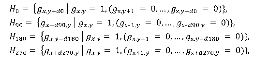
where dα — measured distance along the azimuth α.
The second method does not check for obstacles along the ray path:
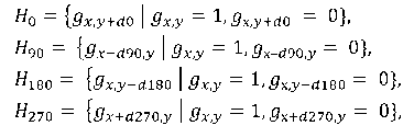
The absence of checks for obstacles along the rays will lead to an increase in the number of estimated positions in the hypothesis sets, which in turn will affect the computation time of their intersection. It is important to note that in the simplified calculation of hypotheses there may be situations when the calculation of positions is performed "through" obstacles, which may result in incorrect final positions.
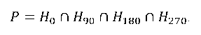
P — set of obtained positions as a result of hypotheses intersection:
Experimental study results
The main difference between the two methods used in the localization process is shown in Figure 1 [1].
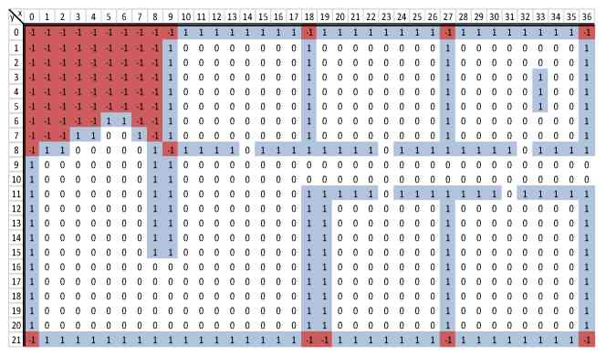
Table 1 shows the results of testing with the map at resolutions of 10, 5, 1, and 0.5 cm. Time 1 — average time of hypotheses calculation, time 2 — average time of hypotheses intersection formation, time 3 - average time of the method execution as the sum of times 1 and 2. Method 2 resulted in a decrease in the time to determine the hypotheses H, but due to the calculation of the intersection P with more hypotheses H, the total execution time of the second method is higher than the first one in most cases.
The first method performed faster than the second method in the cases of the map with resolutions of 10, 5, and 2 cm (814, 3024, 18462 cells, respectively). However, the second method for map resolutions of 1 and 0.5 cm (72992 and 289842 cells) executed faster than the first one.
| Map resolution, cm |
Number of cells, elements |
Method 1 | Method 2 | ||||
|---|---|---|---|---|---|---|---|
| Time 1 | Time 2 | Time 3 | Time 1 | Time 2 | Time 3 | ||
| 10 | 814 | 4140 | 7131 | 11271 | 2978 | 11051 | 14029 |
| 5 | 3024 | 13141 | 13442 | 26583 | 9582 | 29816 | 39398 |
| 2 | 18462 | 65411 | 36089 | 101500 | 37940 | 83614 | 121554 |
| 1 | 72992 | 236010 | 70460 | 306470 | 124234 | 159787 | 284021 |
| 0,5 | 289842 | 903649 | 139280 | 1042929 | 430207 | 338482 | 768689 |
Conclusion
The method provides a way to estimate the coordinates of a device from a known map. However, the result of localization can be ambiguous if there are identical rooms or areas on the map.
The test results showed that the second method was slower than the first one with a small map resolution, but faster with a larger one. By modifying the simplified method with additional verification for each hypothesis, it may be possible to bring its execution time closer to that of the method with full tracking of the measuring beam at a low-resolution map, and make it faster than the simplified method at a high resolution. The considered localization method does not require calculations and storage of the map in the robot's memory. If it is possible to transfer sensor measurement results to a server, calculations can be performed there, thus eliminating the need for large amounts of memory and computational power on the device.
The future goal is to enhance the accuracy of device position estimation. Additionally, it is essential to consider the parameters of sensors, particularly the errors in their measurement results.
References
- Завадская, Т. В. Определение позиции робота по сформированной двумерной карте помещения / Т. В. Завадская, О. И. Креков. – Текст : электронный // Информатика и кибернетика. – Донецк : Доннту, 2023. – №4 (34). – с. 12-18. – URL: https://infcyb.donntu.ru/IC_34.pdf
- Юревич Е. Основы робототехники : учебное пособие [Электронный ресурс] // ЭБ СПбПУ : [сайт]. -URL: http://elib.spbstu.ru/dl/325.pdf
Метод определения позиции робота на двумерной карте помещения. Работа посвящена задаче локализации объекта на известной двумерной карте помещения. Авторами предлагается метод определения местоположения робота, математически описанный в двух вариантах: с отслеживанием хода измерительного луча и без него. Приведено сравнение времени выполнения вариантов метода для карты с разным разрешением.
Ключевые слова: дискретная метрическая карта, локализация, определение местоположения, робот.
Сведения об авторах:
Креков Олег Игоревич — группа КСм-23, магистрант ФГБОУ ВО «Донецкий национальный технический университет»
Завадская Татьяна Владимировна — доцент, к.тех.н, доцент кафедры «Компьютерная инженерия»; заместитель директора НОИ КНТ ФГБОУ ВО «Донецкий национальный технический университет»
Кушниренко Елена Николаевна — старший преподаватель кафедры «Английский язык» ФГБОУ ВО «Донецкий национальный технический университет»
Krekov, O. I. 2D indoor position estimation method for a mobile robot / O. I. Krekov, T. V. Zavadskaya, Ye. N. Kushnirenko. – Text : electronic // Young scientists' researches and achievements in science. – Donetsk : DonNTU, 2024. – pp. 197-203.