
Abstract
Contents
- Introduction
- 1.Actuality of theme
- 2.The purpose and objectives of the research, expected results
- 3.General information and principles of CAD
- 4.Composition and structure
- 5.Analysis of existing CAD systems
- 5.1.ADEM CAD Analysis
- 5.2.T-Flex CAD Analysis
- 5.3.Compass 3D CAD Analysis
- 5.4.AutoCAD CAD Analysis
- 5.5.Autodesk Inventor CAD Analysis
- 5.6.CATIA CAD Analysis
- 5.7.SolidWorks CAD Analysis
- 5.8.The results of the comparison CAD systems
- 6.ObjectARX SDK and JavaScript API
- 7.Advantages and disadvantages of using this approach in the development pipeline CAD
- Conclusions
- References
Introduction
Computer-aided design occupies a special place among information technology. First, design automation - synthetic discipline, its component parts are many other modern information technology. For technical support of computer-aided design (CAD) is based on the use of computer networks and telecommunication technologies in CAD are used personal computers and workstations.
Second, the basic knowledge of computer-aided design and the ability to work with CAD tools required to virtually any developer to the engineer. Computers are full of design departments, design bureaus and offices. Job Designer for conventional panel board, calculations using a slide rule or report design on a typewriter have become an anachronism. Companies leading CAD design without or with only a small degree of their use, are uncompetitive both from the large material and time costs for the design and due to poor quality projects. The appearance of the first programs to automate the design abroad and in the USSR belongs to the beginning of the 60's. Then the program were created to solve the problems of structural mechanics, analysis of electronic circuits, printed circuit board design.
1. Actuality of theme
Now there is an active development of competitive CAD systems [1], the purpose of which is to reduce labor intensity and timing of production at the stages of planning and design, thereby reducing cost and improving the quality of results. Therefore, in the field of CAD is constantly introducing new technologies to extend the capabilities of existing and development of new systems and subsystems of computer-aided design, which gives a significant boost to the development of qualitatively new CAD design methods, analyzing the existing ones.
2. The purpose and objectives of the research, expected results
For the development of its own subsystem of automated piping design were chosen technology ObjectARX SDK and JavaScript API.
The aim of this study have a full and thorough study of selection tools
For the qualitative development of the system or sub-system must be computer-aided design:
- To analyze the principles of creation, composition and structure of CAD.
- Analyse existing software products.
- Identify strategies for further development of optimal methods for constructing complex CAD-systems in CAD pipelines.
- Evaluate the effectiveness of the selected set.
- Make a study of selected methods and the development of relevant technologies of the modern system.
The object of research: CAD pipelines.
Subject of research: analysis and definition of the strategy development using web-based technologies.
3. General information and principles of CAD
The first step is to decide what the design [2].
By design is meant to describe the process of creating a model for the construction of the object does not yet exist in certain circumstances on the basis of the initial description of the object. If this process is carried out by the user when interacting with the computer, it is called automatic.
Consequently, a complex CAD tools for design automation, interconnected with users.
For the design process, there are seven key steps in [3]:
- Pre-research;
- Technical task;
- Preliminary design;
- Technical project;
- Working Draft;
- Making, debugging, testing;
- Commissioning.
The first step is to study the needs of the target audience of users of the system, the automation object compiled a report on the results of research, which is also produced an analysis of existing domestic and foreign counterparts.
In the second stage written technical specification for CAD development, which generates objective, substantiated best option of designing the system, indicating the dates, performers and stages of development.
The subsequent steps are the internal design.
In the third stage developed fundamental solutions for the creation of CAD.
At the fourth stage, developed and approved the final decisions on the creation of CAD and forms of project documentation.
The fifth step involves the creation of CAD documents as a whole and its sub-systems in particular.
The sixth step is assumed manufacture, testing and debugging CAD components and various ancillary tools (e.g., for interfacing peripheral equipment, etc.).
At the final stage of delivery of the project is carried out in a commercial operation, personnel training, CAD integrated debugging, acceptance testing.
From general information about designing move on to the principles of the creation of computer-aided design.
In the technical literature usually distinguish the principle of creating a CAD 4:
- Unity System;
- Compatibility;
- Typing;
- Development.
The first principle is responsible for the integrity of the system and the hierarchy of the design elements.
The second principle ensures the functioning of the components of CAD and their interaction.
The third principle is to unify CAD repetitive elements that have the prospect of repeated use.
Last principle provides scalability and system renewability, as well as interaction with other systems for various purposes.
4. Composition and structure
Aided design systems consist of subsystems, which by means of various technological tools to perform tasks decision in a certain sequence.
Each subsystem is based on a variety of related automation tools, which can be divided into seven types, or as they are called, CAD software types:
- The mathematical software;
- Software;
- Information Support;
- Technical support;
- Linguistic support;
- Methodical maintenance;
- Organizational support;
The first type of provision is based on algorithms that are used in the development of CAD software. They depend on the characteristics of the assets they design, and can be both highly directional, and invariant.
The second type has two subspecies: the system-wide software and special. The first subspecies are operating systems and specific software (for example, the assessment of soil characteristics, etc.) - a special.
The third type is a collection of data that is used for design. This intermediate may be solutions, product specifications, etc.
The fourth type includes not only computers, but in general all of the devices that are required for the design process.
Linguistic support (five species) based on a problem-oriented language designed to describe a computer-aided design procedures.
Under the methodological support (sixth appearance) means a set of documents on the operation of the system. Documents relating to the development, not included here.
The latter type of software is a set of documents relating to the structure of departments, CAD operators, the interaction of these departments together. In a set of organizational documents includes orders, schedules, qualifications, etc.
5. Analysis of existing CAD systems
In this section, the functionality of these systems will be described in [4]:
- ADEM;
- T-Flex;
- Compass 3D;
- AutoCAD;
- Autodesk Inventor;
- CATIA;
- SolidWorks.
5.1. ADEM CAD Analysis
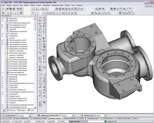
Domestic integrated CAD / CAM / CAE ADEM system [5] is designed to automate the design and technological preparation of production. This single software package, which includes tools for:
- design, product design and simulation;
- Design drawings and design documentation in accordance with the requirements of ESKD;
- Designing technical processes and presentation of technical documentation in accordance with the requirements of ESTD;
- programming CNC equipment;
- archives and project management;
- Renovation of existing knowledge (paper drawings, punched).
We can say that ADEM equivalent to the complex of six professional specialized systems that have a common mathematical core and infrastructure.
Another important component of the system is more than thirty years of experience in the automation of domestic and foreign engineering companies, which in the alloy with modern information technologies determines the reliability and efficiency of the system.
As part of the design and construction of the system ADEM has the most modern tools volume and flat hybrid simulation. The system includes an extensive library of national and international standards of design engineering documentation and standard products.
Ongoing cooperation with leading manufacturers and suppliers of machines and tools, such as:. HANDTMANN, TRUMPF, KUKA Robot Group, the CMD "Pumori-SIZ" CFTechnologies, HAIMER, ISCAR, SANDVIK, SKIF-M, Rost Group, and others in the system constantly improving methods of preparation of CNC programs for the most advanced domestic and foreign equipment.
ADEM allows you to program the following processing techniques:
- Milling 2-5x, including multistage;
- Turning, including multi-spindle and mnogoturetnye;
- Laser 2-5x;
- EDM 2-4x;
- Listoshtampovku and vibrovysechku;
- and combinations thereof.
In this issue of process documentation can be implemented on standard maps and forms (GOST), and the maps and forms of enterprises (STF). As an important complement to perform valuations subsystem and equipment, as well as library materials, equipment and tools.
A special role is played by the integrated system ADEM for technical training, as it covers all the major stages of design and technological preparation of production from first sketch to release details on the machine.
Experience of implementing systems in aircraft, aerospace, instrument, and the nuclear industry shows the high efficiency of the equipment as soon as possible to start and quick payback from the first days of operation of ADEM.
5.2. T-Flex CAD Analysis
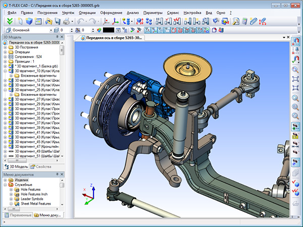
T-Flex - a set of software automation, allowing to cover all stages of design and technological preparation of production. All systems that are part of the complex, fully integrated with each other. The complex contains advanced Russian developments in their respective fields-aided design, which take into account the specifics of Russian production (standards, specifications, equipment and so on. D.). Each of the systems can be operated in combination, in any combination or in standalone mode, which allows you to flexibly and gradually solve the problem of automation of production preparation of any enterprise. An important factor is the cost of the complex. With the same functionality of the cost of the Russian systems is much lower than western.
Tasks:
- automation issue of design and technological documentation;
- creating solid models of parts and assemblies;
- modeling the dynamic behavior of assemblies;
- preparation of control programs for CNC machine tools;
- design of dies, molds, cutting tools and accessories;
- calculation and construction of optimal schemes of cutting parts on the sheet;
- Automation technical document tasks, project management and maintenance of the composition of products.
5.3. Compass 3D CAD Analysis
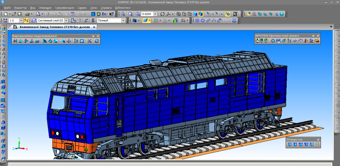
The main problem to be solved by the KOMPAS-3D system - modeling products to significantly reduce the period and the early launch them into production. These objectives are achieved by providing:
- quick design and technological documentation, necessary for production output (assembly drawings, specifications, detail, etc.);
- transmission geometry into design packages;
- transmission geometry in packages of development of control programs for CNC equipment;
- creating additional images (for example, for catalog, creating illustrations for technical documentation, etc.).
The main components of KOMPAS-3D - actually a three-dimensional solid modeling system, drawing and editing and specification design unit. three-dimensional solid modeling system is intended for creating three-dimensional associative models of separate details and the assembly units containing both original and standardized structural elements. The parametric technology allows quickly obtaining models for typical products basing on a once designed prototype. Numerous service functions facilitate the solution of auxiliary problems of design and manufacturing services.
5.4. AutoCAD CAD Analysis
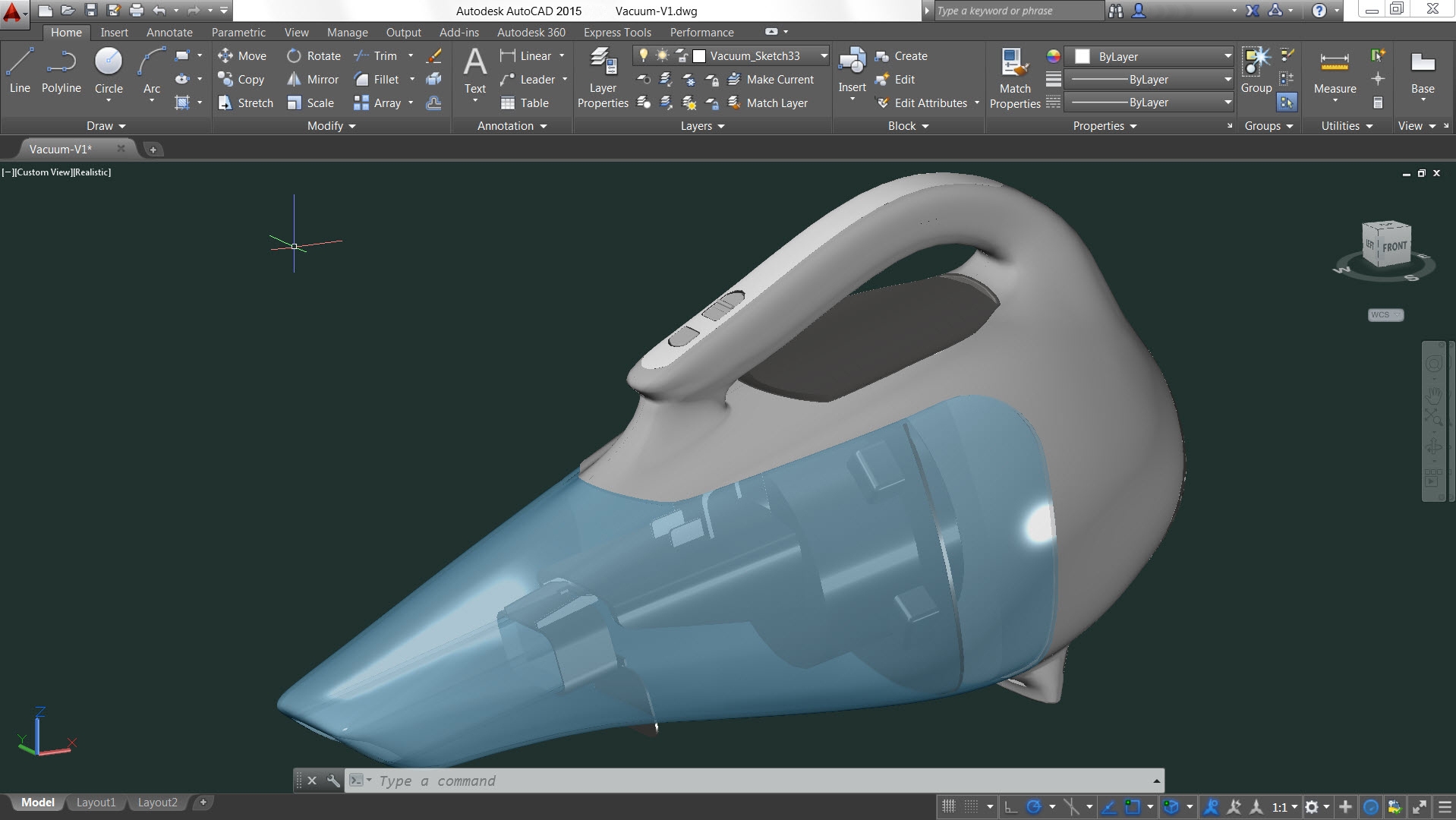
AutoCAD [6] - two- and three-dimensional computer-aided design, developed by Autodesk.
The program includes a complete set of tools that provide a complete three-dimensional modeling, including work with arbitrary shapes, creating and editing of 3D-models of bodies and surfaces, improved navigation and 3D-effective means of production of technical documentation, supports parametric drawing.
Following are some of the functionality of the modern version:
Tools to work with arbitrary shapes allow you to create and analyze complex three-dimensional objects. Their formation and the change is as simple as drag and drop surfaces, edges and vertices.
Three-dimensional printing. You can create physical models of projects through specialized services 3D-printing or personal 3D-printer.
Using dynamic blocks can create duplicate items with variable parameters without having to redraw them again or to work with the library elements.
Zoom function annotative objects in viewports and model space.
Recording of operations allows you to create a sequence of commands, even without programming experience. Recordable operation commands and input value are registered and displayed in a separate window in the tree operations. After you stop recording, you can save the team and the values ??in the operations of the macro file for later playback. When teamwork macros can be accessible to all.
Sheet Set Manager organizes sheets of drawings, makes the publication automatically creates forms, reports data from the filings in the major labels and stamps, and performs tasks in such a way that all the necessary information has been in the same place.
Tools simplified three-dimensional navigation "ViewCube" allows you to switch between standard and isometric views - both predefined and user of the selected point; "Helm" brings together in a single interface, a number of different navigation tools and provides quick access to commands on the rotation orbit, pan, zoom and centering.
Tool "animator Motion" provides access to a named species saved in the current drawing and organized in the category of animated sequences. It can be applied in making presentations project (animated videos) and for navigation.
The user interface supports the ability to customize for specific industry needs. To change the default settings for various AutoCAD functionality, including drawing templates, the contents of the tool palette, workspace.
5.5. Autodesk Inventor CAD Analysis
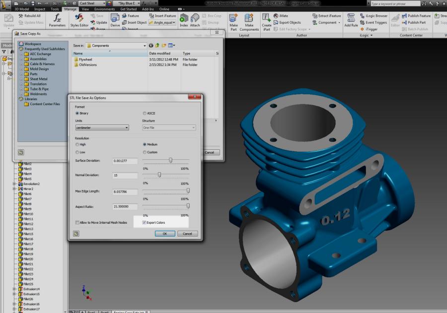
Considered below solid package of engineering simulation engineering products Inventor allows you to work freely with both flat and spatial models.
Ability to work with the flat and spatial models - that's quality compares favorably with Inventor from other CAD systems. The transition from flat to three-dimensional model is possible at any stage of development. Inventor solves the problems of solid modeling of parts, assemblies, release of design documentation - and with it, these problems are solved much faster and more convenient.
The main purpose of the Inventor - provide users with the tools that best meets their requirements, to create conditions for high-performance operation, to ensure the ability to create complex shapes, to ensure that the real requirements of the market in the field of 2D / 3D-design.
Inventor Tools provide a full cycle of designing and creating design documentation
Benefits include:
- adaptive design that enables engineers to design a machine-building profile the natural way for him, just the way they are accustomed to think;
- adaptive layout;
- built-in designer items;
- support systems and interface design process;
- package is easy to learn and has a built-in media assistance funds. The interface includes the design on a sketch-object-level system of training and assistance, including the interactive cinematics;
- possible to design top-down (from the assembly design to design parts that it includes) or upward projection, projecting in one piece at a time. Designers can use both already designed components and schematic based in three-dimensional space, so that you can see in advance how things will work to develop the final version of the relationship of parts;
- when modeling downward (from the conceptual design for elaboration of the final product) it is possible specular reflection and propagation arrays basic body and the working elements (plane axis and a point) - in order to continue to use them to create a real model of the product;
- It has adaptive tool assemblies. When working with large assemblies used adaptive data paging technology; All this happens automatically, without specifying details of the assembly to update them after editing.
Engineering simulation package Inventor has a user-friendly interface that allows you to work intuitively, using the available on-screen graphical icons and hints displayed by the program. interface standards used in the Inventor, similar to Microsoft Windows standards. Inventor allows you to work with both flat and spatial models.
The transition from flat to three-dimensional model is possible at any stage of development. Also, at any time can be returned to the flat model, edit, and save it. In this case there is an automatic restructuring of three-dimensional model. Inventor allows the creation of complex forms with clear and convenient tool palette, as well as ease of assembly parts.
5.6. CATIA CAD Analysis
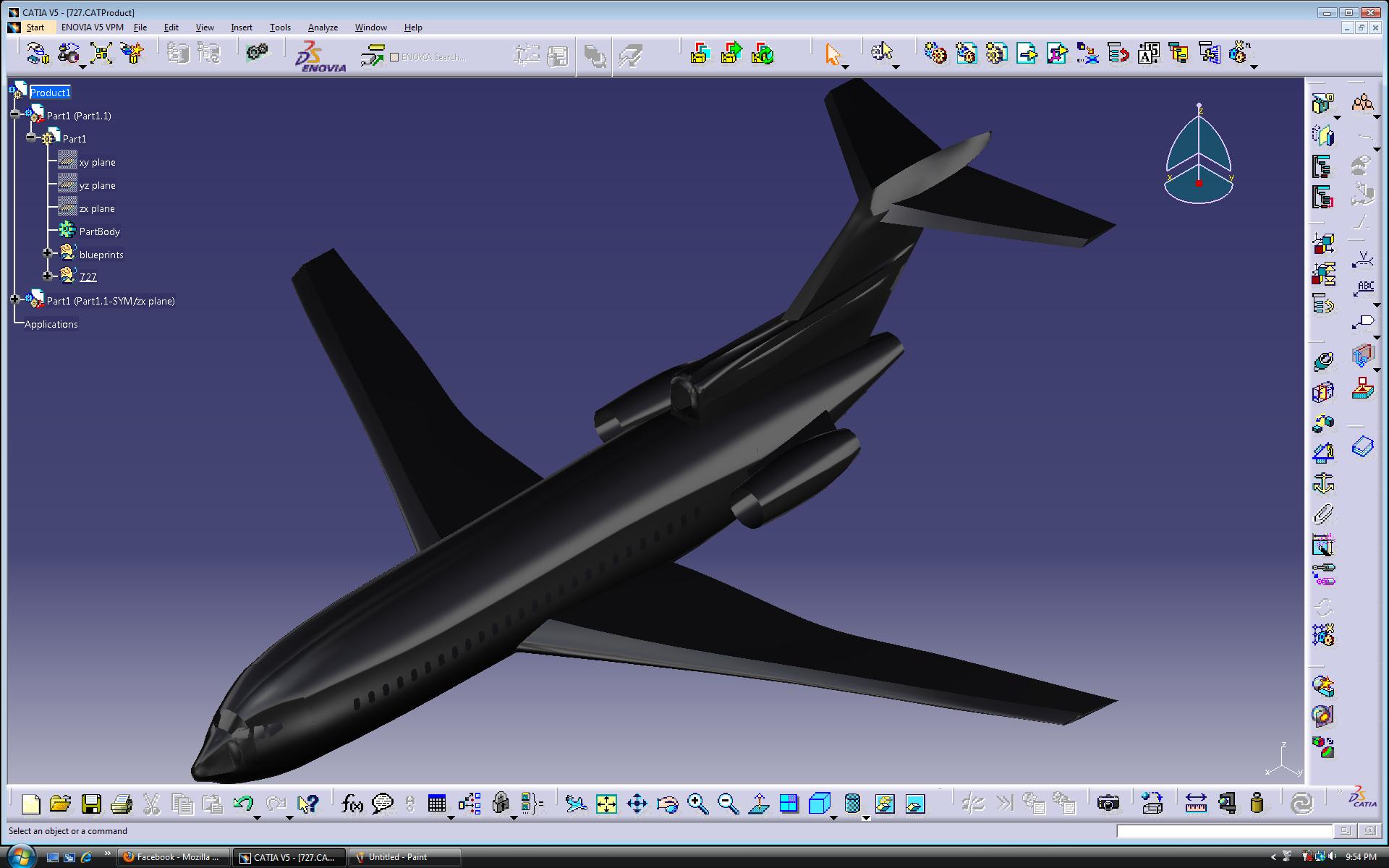
The system CATIA (Computer Aided Three-dimensional Interactive Application) - one of the most common high-level CAD. It is a comprehensive computer-aided design (the product range CAD), technological preparation of manufacturing (CAM) and engineering analysis (CAE), which includes an advanced three-dimensional modeling tools, subsystem software simulation of complex processes, advanced analytics and unified database of textual and graphical information. The system allows you to effectively solve all the technical pre-production tasks - from the outside (conceptual) design to the production of drawings, specifications, wiring diagrams and control programs for CNC machine tools.
Basic CATIA system:
- function works with surfaces;
- the ability to trace the inner wiring trace systems;
- collaborative design (if more than one developer is involved);
- an elaborate system of mapping the structure assembly;
- preparation for rapid prototyping stage, supported by conversion of STL;
- there is a system design of parts, bent sheet metal
- the possibility of kinematic analysis of mechanisms;
- ergonomic analysis is possible as the posture and movement of the field of view of control, distance zones, the control effort;
- thoughtful and quite user-friendly interface.
5.7. SolidWorks CAD Analysis
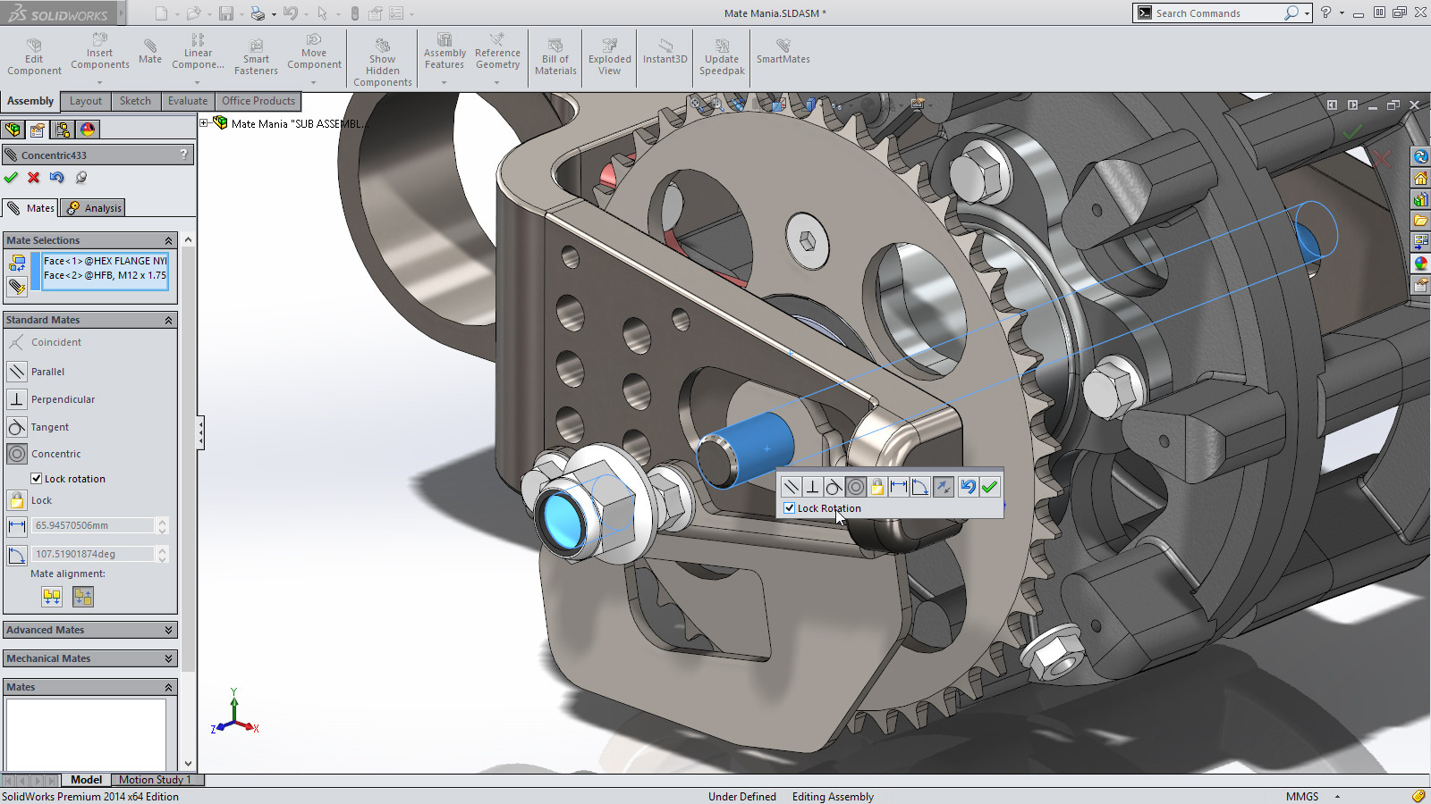
SolidWorks - computer-aided design, engineering analysis and manufacture of products of any complexity and purpose. It is an instrumental environment, designed to automate the design of complex products in engineering and other industries.
SolidWorks is a hybrid system (solids and surfaces), parametric modeling, it is intended for the design of parts and assemblies in three dimensions (3-D design), as well as for registration of the design documentation.
The system refers to the CAD "middle class". SolidWorks is designed to run on PCs with Microsoft Windows system. It has a standard Windows graphical user interface that leverages all the benefits of Microsoft Windows, such as context menus, copy-and-paste mode, drag-and-drop mode, fast browsing, searching and opening files using Windows Explorer, the ability to "rollback" et al. the SolidWorks effectively interact with Windows-based applications such as Excel, Word, and others. The obvious advantages of the system are its complete Russification and support ESKD. In this system it supports all basic standards of presentation and data exchange. The composition of the core SolidWorks package includes more than 20 translators for exporting and importing.
5.8. The results of the comparison CAD systems
After analyzing the functionality provided by CAD systems, we can conclude that all of them support the design in 2D, and in 3D spaces with small differences in functionality. However, very large complex solutions supporting animation (AutoCAD), highly specialized design (ADEM), joint design (CATIA) and other features. Based on the data to create CAD pipeline it was decided to use modern technology development ObjectARX SDK and JavaScript API to AutoCAD platform, which provides the basic features for working with objects in space, as well as saving and loading.
6. ObjectARX SDK and JavaScript API
ObjectARX programming environment is used to adapt and extend the functionality of AutoCAD and products based on it. It provides direct access to the AutoCAD database structures, graphics system, and definitions of built-in commands. With developers can create applications for AutoCAD and other products belonging to this family is object-oriented in C ++ programming interfaces - for example, AutoCAD Architecture, AutoCAD Mechanical and AutoCAD Civil3D [7].
ARX-applications can directly access the data base of the figure and geometric kernel, you can create your own commands, similar to the standard AutoCAD commands. The first package was implemented ObjectARX for AutoCAD R13.
As for the JavaScript API - the programming interface has been added to AutoCAD relatively recently (AutoCAD 2014), so it is an interesting topic for consideration. This interface has been added specifically for that let users [8]:
- Manage the user interface, such as a request for user input and display time;
- Manage current view: zoom, pan, switching visual styles, etc.
- To carry out the implementation of the user interface dialogs using HMTL5, which are connected to AutoCAD with JavaScript.
Thus, JavaScript is the "Internet communication language" that allows you to focus on web-technologies.
In addition, JavaScript API supports a fairly large graphics libraries written in JS (e.g., Three.js), and hence, reduces the threshold to entering the development of various subsystems in AutoCAD for web-developers.
In addition, JavaScript API and ObjectARX SDK can exchange information and to control each other, which allows using the script language to access the database of drawings and database structures.
Among the shortcomings can be noted that the JavaScript API can be slight deviations in the work of some non-core functions because it is quite "young" technology. ObjectARX SDK in turn tested for years, but the C ++ programming language implies self knowledge as a developer of the programming language, and algorithmization when working with 2D and 3D spaces [9].
7. Advantages and disadvantages of using this approach in the development pipeline CAD
In the development of CAD pipelines you plan to use JavaScript API to develop a flexible user-friendly interface, as AutoCad palette using this innovation support HTML5 markup styles [10], which is a very useful tool for the design and implementation of the user interface and its subsequent connection with the AutoCAD commands via the ObjectARX. This approach will provide high speed algorithms of the objects of the scene, because C ++ language and JavaScript is optimized quite well, and allow the system to be portable, scalable and interoperable with other solutions on this platform.
Conclusions
This research describes the basic principles, composition and structure of computer-aided design and analysis of existing software products and defined a strategy for the development of optimal methods for constructing complex CAD-systems CAD pipelines. According to preliminary estimates ObjectARX SDK technology capabilities, JavaScript API, their advantages and disadvantages, as well as of the AutoCAD platform kernel extension which will be this system, we can say that this development is popular, relevant and contemporary.
References
- Program T-FLEX — integrated automation in modern conditions[Electronic resource] - Access mode: http://www.tflex.ru/about/publications/detail/index.php?ID=1187.
- CAD concept [Electronic resource] - Access mode: http://life-prog.ru/1_10018_ponyatie-sapr.html
- Industrial CAD [Electronic resource] - Access mode: http://www.studfiles.ru/preview/987763/.
- Analysis of CAD / CAM / CAE systems [Electronic resource] - Access mode: http://icvt.tu-bryansk.ru/index.php?option=com_content&view=article&id=46:-cadcamcae-&catid=11:-5-&Itemid=31
- ADEM – automation of design and technological preparation of production system[Electronic resource] - Access mode: http://pro-spo.ru/-cad-cam-windows/789-adem.
- AutoCAD [Electronic resource] - Access mode: https://ru.wikipedia.org/wiki/AutoCAD.
- Developing applications for AutoCAD [Electronic resource] - Access mode: http://www.autodesk.ru/adsk/servlet/index%3Fid%3D22740301%26siteID%3D871736.
- Getting Started with JavaScript API on AutoCAD 2014 [Electronic resource] - Access mode: http://adndevblog.typepad.com/autocad/2013/04/getting-started-with-javascript-api-on-autocad-2014.html
- AutoCAD 2014 for Developers [Electronic resource] - Access mode: http://adn-cis.org/autocad-2014-dlya-razrabotchikov.html.
- Connect AutoCAD to the Web with HTML5 and JavaScript [Electronic resource] - Access mode: http://au.autodesk.com/au-online/classes-on-demand/class-catalog/2014/autocad/sd5009.