

Abstract
Сontents
Introduction
The problem of improving the efficiency of heating systems by reducing the wasteful loss of heat from the waste gases is relevant, as is currently the flue gas temperature in the major energy and industrial boiler units is 120 - 160 ° C. Accordingly, the loss of heat waste gases in the preparation of the heat balance of these plants on the lower calorific value of fuel varies from 5-7% to 25-60%.
The widespread industrial, utility and heating plants without heat tail surfaces, with the loss of sensible heat of waste gases amount to 15-20%. Moreover, with the departing gases leave the water vapor, the latent heat of vaporization which amount 10-15% of the net calorific value of the fuel. Total heat loss from the waste gases in the preparation of the heat balance on higher heat value 15-20% in the most improved boiler units. Usually they are the largest of all heat losses, which occur in heating systems.
Various methods for recovery of heat, including deep recovery of heat(using the heat of vaporization) of waste gases in gas boilers and heat exchangers for use contact operation in the autonomous network of heat as the heat generating device. In this case the fuel efficiency is increased by 5-10%. The dependence of the efficiency of the water heater flue gas temperature is shown in Figure 1.
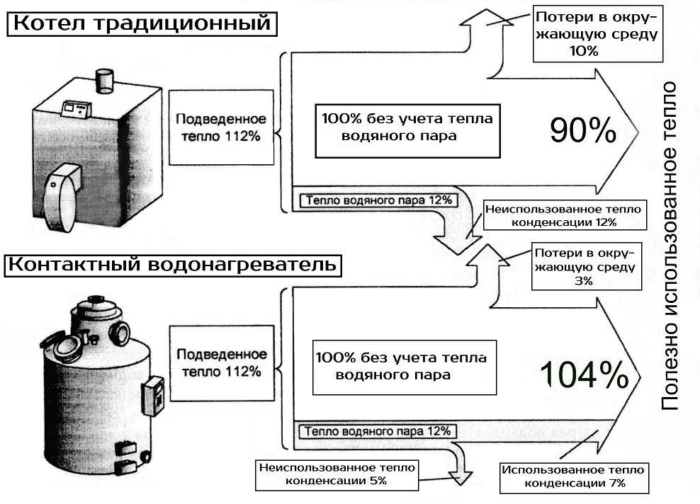
Figure 1 - The dependence of the efficiency of the water heater flue gas temperature.
1. Purpose and problem definition
Temperature of the waste gases in boilers such as TVG-8M, for example boiler room number 367 of Donetsk, is 158 ° C. To solve the problem of lowering the flue gas temperature were analyzed existing utilization plants.
Utilization plants are simple coil heat exchangers, preferably made of pipes with spiral fins (Figure 2), the use of which is about 2 times reduces the size and cost of utilization plants as compared with a smooth one. They are designed for heating water in the heating system or hot water and use the heat of exhaust gases from the furnaces that burn mostly natural gas. Schematic diagram of the utilization plant is shown in Figure 2.
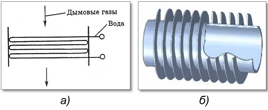
Figure 2 - Schematic diagram of the utilization plant:
a) schematic diagram; b) the tube element
By selecting the fin parameters: the height, thickness and pitch fins and tubes selection step can be adjusted in the heat transfer performance of the finned tubes.
For stable and economical working of the boiler is recommended to maintain the temperature of the flue gas behind the utilization plant is not lower than 90 ° C, and when the two boilers is not below 70 ° C to prevent condensation on the inner surface of the chimney. To prevent condensation of heat water vapor contained in the flue gases, on the heating surface at low temperatures, heated water and its low quality, and there are special circuits and design solution (Figure 3).
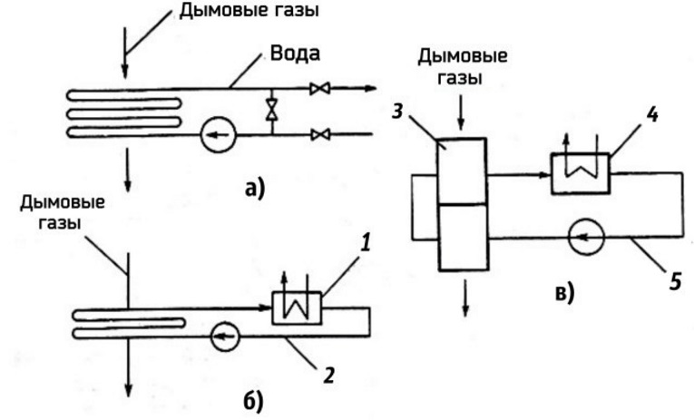
Figure 3 - Schemes of the utilization plants:
a - with recirculating water preheating;
b - with water intermediate circuit;
c - with air intermediate circuit;
1 - water-water boiler, 2 - water intermediate circuit, 3 - air heater,
4 - air-water boiler, 5 - Air intermediate circuit
2. Solution of an objective
Analysis of the heat recovery units showed that the most effective in terms of work at boiler number 367 of Donetsk is heat exchanger TUV-16-10-265 intended for heating water by utilizing the heat of natural gas combustion products from dust, no more than 0.5 mg / m3 in temperate and cold climates. TUV consists of heat-transfer elements, tube sheets, collectors. The heat transfer elements are made of steel carrier pipe and aluminum fins with profile. TUV is in the 10-way version for water attained by means of transverse partitions which create a consistent movement of water through the tubes of the heat exchanger. TUV is set in an underground duct from the boiler №1. The point of connection to the coolant TUV - existing pipelines feedback (the entrance to the boiler), the flow (from the boiler output) system water boiler room №367. In the coolant supply line to the exchanger is installed Magnetic sludge separator. To account for the generated heat is installed ultrasonic flow meter. Location scheme of utilization plant is shown in Figure 4.
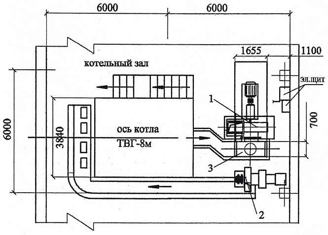
Figure 4 - Location scheme of utilization plant:
1 - exhauster, 2 – ventilator, 3 – utilizator
Conclusion
This choice is considered appropriate because Recovery efficiency increases with increasing load from 1.89 to 4.51%, with a recovery of 0.067 calorific Gcal / h at a pressure of gas burners to 2.9 kPa to 0.37 Gcal / h at a pressure of 12.7 kPa before burners. Thus, the savings share of gas flow from the introduction of waste heat at maximum load is 6.4 m3 / Gcal at the hour of gas savings - 49.32 m3 / h, and the savings in fuel consumption - 12.14 kg fuel equivalent / Gcal. The share of gas consumption when using waste heat decreased by 4.7% relative and amounted to 129.56 m3 / Gcal. Flue gas temperature at maximum load decreased from 183 to 92 °C.
Using allowed for recovery boiler efficiency gains from 1.09 to 4.94% at a temperature of the flue gases after the recovery of 90 ° C and 70 ° C respectively. At the same hour the gas savings, depending on the load was at a temperature of the flue gas after recovery:
- not below 70 ° C ranged from 20.15 to 55.87 m3/h,
- not below 90 ° C ranged from 5.74 to 42.33 m3/h.
References
Lipiec A.U. Disposal of waste heat from industrial furnaces flue gases // Thermal Engineering. 1999. №4
Aronov I.Z. Contact gas economizers // Kiev: Technics 1964.
Korolevich А.Y., Yurchenko M.M. Heating and hot water in local heat networks on the basis of the contact water heater // Energy saving. 2002. №5.