


|

KONDRATUEVA NATALA ARKADYEVNA
(TATARINSKAYA)
Ňheme:
"USING THE METHOD OF 3M MODELLING FOR ESTIMATION THE INERTIAL CHARACTERISTICS OF HEADING MACHINES"
Science supervision:ph. V.P. Kondrahin
For modeling the working processes and decision the problems of statics and dynamics heading machines, the great value has knowledge of inertial characteristics to which it is possible to relate weight, coordinates of the center of weights, the moments of inertia, direction of the main axes of inertia.
Modern packages of three-dimensional designing allow to define inertial characteristics of constructed model with any degree of accuracy.
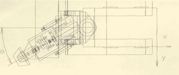
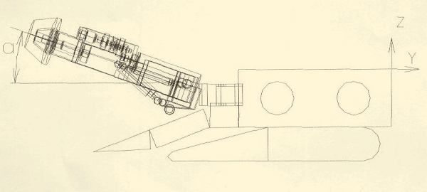
In the present work were researched the inertial characteristics of the heading machine with an arrow-type rock breaker, for that was developed the three-dimensional model of a combine (see pic.1). At creation of model were taken up the following simplifications:
- Shaft and an axis haven't facets, key slots, flutes for a grinding wheel's exit;
- There are no fastening elements , elements of hydraulics: branch pipes and hoses;
- Cutting tools (CT) are showed without cutters and tool heads;
- Cogwheels are submitted as disks which basic sizes are: width of a ring gear, dividing diameter and diameter of a shaft;
- The case, caterpillar mechanisms of movement and hydrojacks are conditionally submitted as the homogeneous bodies, which density are:
p = M / V,
where M - real weight from the subunit drawing;
;
V - volume of solid-state model.
With the help of the constructed model were determined the basic inertial characteristics of a combine, such as coordinates of the center of weights, the moments of inertia concerning axes, the centrifugal moments of inertia, the main central moments of inertia (table 1, 2 and 3) depending on position of the cutting tool in excavation's space (here a - a corner of cutting tool inclination in a vertical plane, and b - in horizontal).
Table 1 - the basic inertial characteristics of the heading machine 4PP-2Ě depending on change the position of the cutting tool in vertical plane ( b = 0)
| a ,degrees |
Coordinates of the center of weights, mm |
Radiuses of inertia, mm |
The moments of inertia concerning axes, kg *2 |
| Xc |
Yc |
Zc |
rx |
ry |
rz |
Ix |
Iy |
Iz |
1 |
2 |
3 |
4 |
5 |
6 |
7 |
8 |
9 |
10 |
| 0 |
-1000 |
2760 |
-882 |
1902 |
887 |
1953 |
116600 |
25400 |
122900 |
| 10 |
-1000 |
2758 |
-845 |
1911 |
916 |
1948 |
117700 |
27000 |
112270 |
| 20 |
-1000 |
2750 |
-810 |
1911 |
956 |
1940 |
117700 |
29300 |
121270 |
| 30 |
-1000 |
2734 |
-776 |
1914 |
1004 |
1918 |
118000 |
32500 |
118500 |
| 38.5 |
-1000 |
2726 |
-747 |
1923 |
1050 |
1889 |
119100 |
35500 |
115000 |
Continuation of the table 1
| a ,degrees |
The centrifugal moments of inertia, kg*m2 |
The main central moments of inertia, kg*m2 |
| Ixy |
Izx |
Izy |
Ixx |
Iyy |
Izz |
11 |
12 |
13 |
14 |
15 |
16 |
| 0 |
88900 |
-28400 |
-78400 |
270500 |
57280 |
277660 |
| 10 |
88860 |
-27200 |
-75100 |
268100 |
55200 |
277300 |
| 20 |
88600 |
-26100 |
-71800 |
264800 |
53360 |
275900 |
| 30 |
88100 |
-25000 |
-68400 |
260200 |
51600 |
275900 |
| 38.5 |
87800 |
-24100 |
-65600 |
257400 |
50200 |
271600 |
Table 2- the basic inertial characteristics of the heading machine 4PP-2Ě depending on change the position of the cutting tool in horizontal plane (a = 0)
| b ,degrees |
Coordinates of the center of weights, mm |
Radiuses of inertia, mm |
The moments of inertia concerning axes, kg*m< sup>2 |
| Xc |
Yc |
Zc |
rx |
ry |
rz |
Ix |
Iy |
Iz |
1 |
2 |
3 |
4 |
5 |
6 |
7 |
8 |
9 |
10 |
| 0 |
1000 |
2760 |
-882 |
1902 |
887 |
1953 |
166600 |
25300 |
122900 |
| 10 |
948 |
2738 |
-882 |
1871 |
899 |
1928 |
112800 |
26000 |
119700 |
| 20 |
900 |
2708 |
-882 |
1826 |
930 |
1898 |
107400 |
27900 |
116100 |
| 30 |
859 |
2670 |
-882 |
1690 |
1029 |
1822 |
92000 |
34100 |
107000 |
| 38.5 |
812 |
2615 |
-882 |
1690 |
1029 |
1822 |
92000 |
34100 |
107000 |
Continuation of the table 2
| b ,degrees |
The centrifugal moments of inertia, kg *m2 |
The main central moments of inertia, kg *m2 |
| Ixy |
Izx |
Izy |
Ixx |
Iyy |
Izz |
11 |
12 |
13 |
14 |
15 |
16 |
| 0 |
88930 |
-28400 |
-78400 |
270500 |
57300 |
277700 |
| 10 |
83630 |
-26900 |
-77800 |
266600 |
54000 |
270500 |
| 20 |
78500 |
-25600 |
-77000 |
261300 |
51200 |
262400 |
| 30 |
73900 |
-24400 |
-75900 |
254800 |
48800 |
253500 |
| 38.5 |
69000 |
-23300 |
-74300 |
245400 |
46700 |
244300 |
Table 3 - the basic inertial characteristics of the heading machine 4PP-2Ě in extreme positions of the cutting tool in excavation's space
| b degrees, |
a ,degrees |
Coordinates of the center of weights, mm |
Radiuses of inertia, mm |
The moments of inertia concerning axes, kg *m2 |
| Xc |
Yc |
Zc |
rx |
ry |
rz |
Ix |
Iy |
Iz |
| 1 |
2 |
3 |
4 |
5 |
6 |
7 |
8 |
9 |
10 |
11 |
| Extreme bottom positions of the cutting tool |
| 42 |
-21.2 |
-1225 |
-2676 |
-993 |
1760 |
1030 |
1890 |
10000 |
34200 |
116100 |
| 42 |
-21.2 |
-775 |
-2659 |
-957 |
1740 |
1050 |
1890 |
97100 |
35300 |
114800 |
| Extreme upper positions of the cutting tool |
| 42 |
38,5 |
-1208 |
-2657 |
-817 |
1780 |
1090 |
1850 |
102100 |
38700 |
110300 |
| 42 |
3805 |
-787 |
-2647 |
-765 |
1806 |
1172 |
1846 |
104400 |
44100 |
110300 |
Continuation of the table 3
| b ,degrees |
a ,degrees |
The centrifugal moments of inertia, kg *m2 |
The main central moments of inertia, kg *m2 |
| Ixy |
Izx |
Izy |
Ixx |
Iyy |
Izz |
12 |
13 |
14 |
15 |
16 |
17 |
Extreme bottom positions of the cutting tool |
| 42 |
-21.2 |
105600 |
85600 |
39200 |
262500 |
80100 |
279000 |
| 42 |
-21.2 |
103400 |
69900 |
31800 |
249000 |
68500 |
274500 |
| Extreme upper positions of the cutting tool |
| 42 |
38,5 |
66600 |
82000 |
23900 |
257300 |
49000 |
247300 |
| 42 |
38.5 |
67100 |
65200 |
16400 |
444600 |
38800 |
245700 |
On the dates, which resulted in tables 1 and 2 it is possible to make the following conclusions.
Coordinates of the center of weights change at change the position of the cutting tool in excavation's space .
Change relatively the X coordinate, at the increase in a corner of an inclination of the cutting tool in the vertical plane from 0 up to 38,5deg., is slightly (0,2 mm), and at change of a corner of turn of the cutting tool in a horizontal plane from 0 up to 42 degr. reach 181 mm. These changes don't exert influence on the transverse stability of the combine, because the caterpillars-width of a combine is 2400 mm.
Displacements about Y coordinate are:
- At increasing the corner of an inclination of cutting tool l in vertical plane - 34 mm;
- At change the corner of turn the cutting tool in a horizontal plane - 145 mm.
It is also doesn't exert influence on a stability of the machine, because e longitudinal sizes of a combine's basic base are considerable. Besides longitudinal stability of the combine increases at the expense of the leaning on the end of a feeder's basic table .
At the change of the cutting tool position there is an essential change of the moments of inertia.
We shall analyze, for an example, change of the main central moments of inertia:
- At the change of the cutting tool position in vertical plane Ixx changes from 270500 kg*m2 up to 257400kg*m2 (on 5%) , Iyy from 57280 kg*m 2 up to 50200 kg*m 2 (12%), Izz from 277660 kg*m 2 up to 271600 kg*m2 (2%).
- At the change of the cutting tool position in a horizontal plane of excavation's space, the main central moments of inertia changes about X axis from 270500 kg*m2 up to 245400 kg*m 2 ( 9%), Iyy from 57300 kg*m 2 up to 46700 kg*m 2 (18%), I zz from 277700 kg*m 2 up to 244300 kg*m 2 (12%).
It is necessary for taking into account at the modelling the working processes of the heading machine.
In such a way , using a method of 3Ě modelling were received input dates for modelling the working processes of the heading machine, with the purpose of optimization a parameters of powersubsystems, systems of their automatic control and operating modes.
Literature:
1. Kondrahin V.P., Efremov M.A. Estimation the inertial characteristics of mountain machines//Students scient.-techn.magazin ą4.-Donezk:DonNTU,2003.-p.120-122.
2. Solod V.I.,Gettopanov V.N., Rachek V.M. Desining of mountain machines.-Ě.,Nedra, 1982, 350 p.
UP
|


