


ТТR00-А / Geological Faculty
Magister's work topic: "Development of a shell for liquidation sticking in a prospecting chink"
Instructor: Karakozov Artur Arkadyevich
 malik_tanya@ukrtop.com


Relevancy of work
The construction of a well is a labour-intensive engineering-technological process attended by various accidents which reduce labour productivity and increase drilling work prime cost. Every year 5–10% of working time is spent for the elimination of accident consequences. Usually the accidents are the reasons for writing-off of wells which have not fulfilled their geological task.
That is why the problem of creation of accident elimination mechanisms in exploration wells has been relevant during many years.
All the devices being created have to correspond to the small sizes of modern wells and to join quickly and easily to the drill string while crossing the sticky zones. Taking into account the necessity of further technical re-equipment of geological exploration organizations and their equipping with high-performance equipment and facilities, the devices for prevention and elimination of sticking should also correspond to the world standards and norms.
Due to the analysis of accidents which take place during the drilling of stratigraphic test wells and exploratory wells for oil and gas, the specialists can determine now the most typical sticking types and probable causes of their occurrence. About 26% of stickings occur as a result of pressure differential (1st category according to A.K. Samotoy’s classification), 32% of them occur as a result of jamming of implements (2d category) and 42% occur because of well narrowing caused by the screes, caving, packing, sliding of cuttings and loading material (3d category). The same situation takes place in geological exploration sphere, except the sticking of 1st category, which is not so wide spread here as during drilling the wells with major diameter.
The correlation of sticking data shows the occurrence of typical accidents caused by the same reasons and having the same severity. However, the higher level of selectivity of sticking elimination methods and technology, especially percussive mechanisms, allows the foreign specialists to reduce considerably the expenditure of time and resources for sticking elimination. In the domestic practice the percussive mechanisms for sticking elimination (PMSE) have been used for the last 25-30 years. But their use is limited, especially in geological exploration sphere in which the percussive mechanisms are not even included in the list of necessary emergency technical devices. At the same time the statistics shows that the use of PMSE during the drilling of oil and gas wells is very efficient especially by the 2d category sticking elimination by which the probability of stuck tool retrieving comprise 0.7. The use of jars with different operating principles is very efficient by the elimination of 3d category sticking. In this case the most effective result is obtained by emergency tool processing with impact impulses in combination with the violent reciprocation of the tool or installation of liquid baths.
The use of jars in combination with other methods (e.g. installation of oil baths) for elimination of sticking caused by pressure differential (1st category) can also have positive results.
Thus, the design features and versatility of the percussive mechanisms which are reliable by the elimination of a number of sticking types show the perspectives of the given class of machines. Besides, the work experience of organizations of the Ministry of Oil Industry in construction of PMSE can help in creation of the efficient mechanisms for the wells of minor diameter.
In Donbass the wells are mainly drilled in the areas of coal mines where there are a great number of lost-circulation zones caused by mining work. As a result, the possibility of sticking occurrence caused by the lost return increases manifold.
The use of jars in these conditions can turn things worse because the vibrating drill string can ruin the well walls not filled with liquid.
There are the percussive mechanisms which produce hydrostatic pressure of liquid column in the well. In this case the drilling string does not take up dynamic loads, i.e. does not take part in vibrating system. However, neither of them can be used in aforesaid conditions because the previously produced mechanisms are not used for jarring the stuck drilling string in the wells with low liquid level above the well bottom or in the empty wells. Such situation takes place in the wells which cross the zones of disastrous lost circulation, e.g. zones of previous mine openings. In such devices the anvil block blow energy addressed to the stuck drilling string depends on the hydrostatic pressure in the well.
The purpose of job
That is why the task of the given master’s thesis work is the development of percussive mechanism for elimination of sticking of the drilling strings in wells with low static fluid level which produces hydrostatic pressure of liquid column in the drilling pipes.
Main tasks.
The master’s thesis work represents a part of research work on the creation of technical devices for drilling of wells in abnormal conditions carried out by the Department of Technology and Principles of Geological Exploration.
Theoretical analysis.
The methods of engineering analysis of speed of the percussive mechanism anvil block which creates the differential pressure between the well and drilling pipes have been worked out.
It is recommended to take into account the liquid compressibility when setting up an equation of anvil block motion while calculating the operating cycle with the well depth over 100m.
The differential equation of motion of the percussive mechanism anvil block which creates the differential pressure between the well and drilling pipes is set up in the following way, taking into account the elastic properties of liquid:
where m – anvil block mass;
р – liquid density;
с – speed of hydro percussion wave propagation;
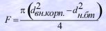
F – square of anvil block;
V – speed of liquid transfer out of well to the percussion mechanism;
h – liquid level in the drilling string;
H – liquid level in the well;
G – anvil block weight;
R – total mechanical resistance arising when the anvil block in the cylinder of mechanism is in motion.
The given equation is to be solved together with Bernoulli equation for the non-steady liquid flow by the crossflow of liquid from the well to the cylinder of mechanism. Simultaneous solution of these equations gives us the following:
For empty wells with Н = 0:
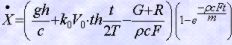

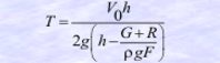
Vo – maximum speed of liquid crossflow to the cylinder of mechanism.
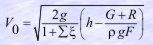
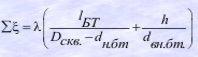
?? total liquid resistance coefficient. It is defined according to actual well design:
T – shorthand notation:
Description of the proposed mechanism design.
The mechanism being used for elimination of drilling string sticking consists of drilling string body with radial holes and shoulder on the inner surface, piston-rod concentrically assembled in it with anvil, rod stop on the outside surface, axial canal, seating for inverted valve and two rows of radial holes situated between the rod stop and the seating for inverted valve, anvil block situated between the anvil and the piston-rod stop, and baffle plate situated below the anvil block. The additional baffle plate is situated in the drilling string body. In its hole the axial moving nozzle with lugs situated between the anvil and additional baffle plate is assembled. The lower part of this nozzle is fixed in the rod axial canal and connected to the hollow-bore piston situated above the seating for inverted valve and opposite to the upper row of rod radial holes. The upper part of the nozzle is connected to the bowl situated above the additional baffle plate. At the same time the baffle plate under the anvil block with the valve fixed in it is situated between 2 rows of rod radial holes and connected to the rod. The radial holes of the drilling string body are situated above the anvil block. The seating of inverted valve in the rod is turned to the nozzle. The nozzle lug and the bowl are made taking into account the possibility of periodical interaction with the additional baffle plate.
The mechanism operates in the following way.
It is being used in the wells with low drilling liquid level above the well bottom, for e.g. during the drilling of dirt beds with extreme lost return. Upon the occurrence of sticking in the well the mechanism is being moved down to the stuck object with the help of drilling pipes connected to the drilling string body. In this case the inverted valve in the mechanism is missing. If necessary, the bottom-hole is flushed through the axial canals of the mechanism. If the mechanism with stuck drilling string is connected to the piston-rod which can be additionally attended by the finger grip, the rotation of the drilling pipes is transmitted to the piston-rod through the drilling string body, reducing socket and slotted joint. After that the inverted valve is being dropped in the drilling pipes and it gets to the valve seating and secures the axial canal in the piston-rod. The bowl helps the valve to get to the piston-rod canal. Then the drilling pipes are filled with drilling liquid with the help of pump in such a way that the liquid level in the pipes is higher than the liquid level in the well. The valve prevents liquid from leaking out from drilling pipes, that is why the pot under the baffle plate is filled with liquid through the holes and the piston-rod canal over and under the plunger-piping is filled with liquid through the nozzle canal and the canals 22, 17, 23 accordingly. The anvil block remains on the rod stop under gravity and under pressure of drilling liquid in the well. The anvil block is connected to the well by canals made in the drilling string body and detached from canals of drilling pipes by the anvil having the form of plunger-piping.
For jarring the drilling pipes are supplied with voltage and the drilling string body is lifted to the uppermost position until the lower reducing socket contacts the baffle plate valve. The additional baffle plate interacts with the bowl and lifts it up. Thus, the nozzle is lifted up together with hollow plunger piping and it discloses the upper row of radial holes in piston-rod. The liquid starts to flow from canals of drilling pipes to the anvil block through the axial canal of the nozzle and holes. As the pressure under the anvil block is higher than the pressure over it because the liquid level in the drilling pipes is higher than the liquid level in the well, the anvil block moves upwards and hits the anvil. In this case the liquid is displaced from the canal situated over the anvil block to the well through the holes.
In order to hit the anvil once again the drilling pipes are moved down. The shoulder of drilling string body presses down on the anvil block and moves it down to the rod stop. In this case the liquid is displaced from under the anvil block to the canals of drilling pipes through the holes. When the additional baffle plate presses down on the nozzle shoulder the nozzle moves down until its shoulders contact the anvil. In this case the plunger covers the canals and displaces the liquid from under the anvil block to the canals of drilling pipes through the valve and holes as the lower reducing socket unseats the valve.
The hits transferred to the stuck drilling string during the operation of mechanism release the drilling string from sticking.
During the operation of mechanism the canals provide free flow of liquid to the mechanism cavities situated over the hollow plunger piping and anvil.
The mechanism can also be attached to the drilling string. In this case the inverted valve of mechanism is missing while drilling. The pins transmit the rotary moment to the well bottom and the shoulders transmit the thrust force to the anvil block and rod stop. If the sticking occurs, the inverted valve is being dropped in the drilling pipes and gets to its seating. The following operation of mechanism is the same.
Application technology.
The mechanism can be used in two ways:
- after the accident;
- as a part of drilling string while redrilling the sticky zones.
The following processing sequence is to be followed while using this mechanism after the occurrence of sticking:
After the accident elimination the well is being flushed out for 20-30 minutes and the drilling string is being lifted to the surface.
If the drilling string is not released from sticking after 50-60 hits, the operation of mechanism must be stopped, the stuck drilling string must be detached and its loose part must be lifted to the surface.
If the use of this mechanism has negative results it is possible to reuse it after oil or acid spotting operation in sticky zones.
In case when the mechanism is used as a part of drilling string, it is to be mounted over the core-barrel and detached reducing socket. If the accident takes place, the ball valve is being dropped through the drilling pipes and the operation repeats according to aforesaid steps 5-8.
PROSPECTS OF THE FURTHER RESEARCHES
The mechanism being developed has a significant advantage – it can be used in the wells with low liquid level above the well bottom or in the dry wells. However, the disadvantage is that this mechanism can not be used in the wells with high liquid level.
In future the mechanism for accident elimination is supposed to be developed. It will be possible to use this mechanism in the wells either with low or with high liquid level.
Nowadays the refined numerical scheme of mechanism’s operation cycle is worked out.