Ссылки
Отчет о поиске
Автореферат
Библиотека
О Мальте
Кафедра
Факультет
ДонНТУ
Polytechnic University of Bucharest, Romania Department of Electrical Engineering
Constantin Ilas
Real time identification of induction motor drives
PhD Thesis Compendium
Supervisor: Professor R. Magureanu
1995
Part II: State Identification in Direct Field Oriented Induction Motor Drives
Rotor flux identification is determinant for the performance of any DFOC system, no matter how complex this is. That is why it is the first discussed. Moreover, the results obtained in this part are very important for understanding and comparing different solutions of state and parameter simultaneous identification problem.
II.1. Observers Obtained by Solving Motor Equations
In these observers rotor flux components are expressed by solving the continuos time model (I.1.) equations. They are named according to the input quantities, as follows:
Observers Using Stator Voltages and Currents (VI Observers)
The flux is obtained from stator equations:

Observers Using Stator Currents and Motor Speed (Iw Observers)
It is given directly by the last two rows in (I.1.):

Observers Using Stator Voltages and Currents, and Motor Speed (VIw Observers)
Introducing: 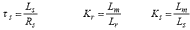 , its equations are:
As one may see, they are not (except the second) in state space form. This is why obtaining their discrete equivalents assumes an integral discrete evaluation, trough one of the known methods [17]. The first and the third imply the integral of the stator voltage first harmonic. Since the voltage is the output of a PWM inverter, the errors in its measurement will decrease this observers performance.
II.2. Linear State Observers (Luenberger Observers)
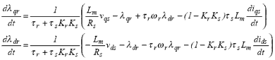
They are given by the general state estimation theory [8]. With notations explained in I.4., a full continuos or discrete observer is given by:

where the gain matrix L controls the observer pole placement, as it is demanded by stability, dynamics, noise sensitivity conditions. As for the induction motor the A matrix has variable parameters, L has to assure these conditions for any parameters value. Usually this is done trough some relations assuring a proportionality of matrix A and observer poles ([47]-[48]). Each sampling time the matrix gain for the continuos time observer is thus computed, and then its discrete equivalent is obtained. For the considered motor, the discrete observer root locus in the extreme presumption that its poles are equal to those of matrix A, is shown in Fig. II.1.a. This pole placement method has the following drawbacks:
1) the observer dynamic is not very good neither for very low nor for high speed;
2) for very low speed computation errors may lead to an unstable behavior ;
3) it needs an important time, especially for discrete equivalent calculation.
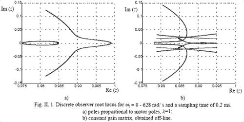
Fig. II. 1. Discrete observer root locus for wr = 0 - 628 rad/ s and a sampling time of 0.2 ms. a) poles proportional to motor poles, k=1; b) constant gain matrix, obtained off-line.
We propose a new off-line method that gives a constant discrete gain matrix L so that drawbacks 2 and 3 are canceled. The new root locus is presented in Fig. II. 1.b.
Автобиография | Ссылки | Отчет о поиске | Автореферат | Библиотека | О Мальте