[Main page]
[Master's work]
[Links]
[Report about the search]
[Individual task]
Single-phase half-controlled thyristor bridge
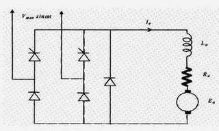
A half controlled bridge converter has two thyristors
and two diodes in the bridge arms, and a additionally a commutating diode across
the motor terminal to allow the thryristor current to commutate into when the
AC supply voltage reverses polarity. The commutating or freewheeling diode is
required to prevent unconrolled operation of a bridge arm. The presence of the
freewheeling diode circulates ( freewheels ) the armature current and prevents
the load voltage from becoming negative.
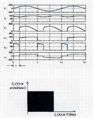
Where continuous conduction has been assumed. The half
controlled converter has the desirable attribute that it presents a higher input
power factor than the fully controlled converter. This is because the lagging
current of the source current is contrained to flow locally through the motor
circuit by the freewheeling diode. Its output voltage and current ripples are
also lower and the armature current is likely to become disconitnuos, so that
the crtical inductance required for continuous conduction is not as large. The
gate drive and converter circuit costs are also somewhat cheaper. It however
operates in one quadrant only, so regenerative braking of the drive is not possible.
Three-phase, fully-controlled thyristor
bridge converter
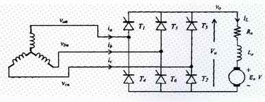
For larger DC motor drives, three-phase thyristor converter
circuits are preferred due their better output ripple and input harmonic performance.
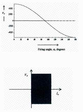
This converter operates in quadrants 1 and 4, developing
both positive and negative polarity dc output voltage. For firing angles 0° < а < 90°, the converter operates in quadrant 1 and for
90°< а <180° the operation is in quadrant 4. Operation in quadrant 4 is of course possible
only when the load includes an active dc source, able to source power into the
ac circuit.
of the Three-phase bridge converters circuits
have the following attributes, compared to the single-phase bridge converter:
1. The output voltage waveform of the converter is smoother, having the lowest harmonic order of six acopared to two for
the single-phase bridge converter. The ripple voltage to the motor have harmonic order or 6k where k is any
positive integer. The armarure current ripple has the same harmonic order. The ripple voltage and currents are also of lower magnitude. The
highest output ripple occurs for а = 90°.
2. The lower ripple in the armature current and the smoother voltage waveform calls for smaller armature inductance which may be required to
ensure continuous conduction.
3. The effective converter switching frequency is six times the supply frequency ( 300 Hz, compared to 100 Hz for a single-phase bridge converter ).
4. The input current waveform to the converter is more closer to being a sinusoid ( i.e., better distortion factor ), compared to the input current waveform
for the single-phase ridge converter. The harmonic order of the AC input line current is given by 6к ±1, compared
to em>2к ± 1 for the single-phase converter, where k is any positive integer.
This calls for reduced filter requirement at the input AC side.
Armature current for continuous conduction
The motor current can be exactly determined from the DC and harmonic currents, using DC and AC circuit analysis
techniques and then adding the currents for each voltage component. Alternatively, for the interval
а + 30° <соt < а - t - 90° assuming a constant back emf.
Note that the output voltage wavefrom repeats every 60°.
From the complete solution of the armature current, the average and RMS armature current can be determined.
For the average armature current, the motor developed torque is found, for the speed for which Ea was used in the calculation.
Torque-speed characteristic with continuous conduction
For a given firing angle а, the Т-w
characteristics are given by,
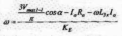 , where L3х
is the equivalent source reactance of the three-phase AC source.
, where L3х
is the equivalent source reactance of the three-phase AC source.
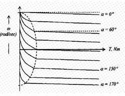
Note that operation in quadrant 1 is for forward driving and operation in quadrant 4 is for reverse (regenerative) braking.
The droop in speed with load is partly due to the voltage drop in armature resistance and partly due to the voltage regulation characteristic of the converter as
a consequence of the AC side source inductance. The steeper drop in speed indicated by the graphs to the left of the semicircle are due to discontinuous
conduction.
The critical inductance
As for the single-phase converter, the armature current can become discontinuous, depending on the load,
firing angle and motor parameters. The boundary between continuous and discontinuous conduction is found from equating.
This is indicated by the dotess semicircle in the Т-w plane in the above figure.
The critical inductance for just is discontinuous conduction.
Operation with discontinuous Conduction
When the armature current becomes discontinuous, the motor terminal voltage rises to the level of the back emf, instead
of following the AC line-line voltages. The effect is a net increase in the average voltage across the motor and hence speed. If the armature current falls
to zero at angle а + у, where у is the conduction angle, the solution for the armature current for this condition operation is
found by noting the 4 at а zero in a thyristor is triggered. Current ia becomes zero at а + у.
[Main page]
[Master's work]
[Links]
[Report about the search]
[Individual task]