| Russian |ÄîíÍÒÓ| Ïîðòàë ìàãèñòðîâ ÄîíÍÒÓ|


  Â ýëåêòðîííóþ áèáëèîòåêó 

    http://link.aip.org/link/?JMSEFK/122/32/1

    HIGH SPEED GRINDING OF SILICON NITRIDE WITH ELECTROPLATED DIAMOND WHEELS, PART 1: WEAR AND WHEEL LIFE

    T. W. Hwang, C. J. Evans, and E. P. Whitenton
    Manufacturing Engineering Laboratory, National Institute of Standards and Technology, Gaithersburg, MD 20899
    S. Malkin, Distinguished Professor, Fellow of ASME
    Department of Mechanical and Industrial Engineering, University of Massachusetts, Amherst, MA 01003
    (Received Dec. 1998; revised June 1999)

An investigation is reported on high speed grinding of silicon nitride using electroplated single-layer diamond wheels. This article is concerned with wheel wear and wheel life, and a second paper (ASME J. Manuf. Sci. Eng., 122, pp. 42–50) deals with wheel topography and grinding mechanisms. It has been suggested that grinding performance may be enhanced at higher wheel speeds due to a reduction in the undeformed chip thickness. Grinding experiments were conducted at wheel speeds of 85 and 149 m/s with the same removal rate. Contrary to expectations, the faster wheel speed gave no improvements in surface finish, grinding ratio, or wheel life. Microscopic observations of the wheel surface revealed dulling of the abrasive grains by attritious wear, thereby causing a progressive increase in the forces and energy until the end of the useful life of the wheel. For all grinding conditions, a single-valued relationship was found between the wheel wear and the accumulated sliding length between the abrasive grains and the workpiece. A longer wheel life and improved grinding performance can be obtained when the operating parameters are selected so as to reduce the abrasive sliding length per unit volume of material removal. [S1087-1357(00)00301-4]
1 Introduction
Silicon nitride is an advanced structural ceramic with high strength and toughness at both ambient and elevated temperatures and good wear and corrosion resistance. The superior properties of silicon nitride has led to its being considered as a replacement for metals for some industrial applications including cam followers, hybrid bearings, pump seals, and blades in high temperature stationary turbogenerator sets. Machining of silicon nitride and other ceramic components to the shape that is required generally necessitates grinding with diamond wheels. Widespread utilization of advanced structural ceramics has been constrained mainly by high grinding costs and the possibility of causing damage to the workpiece during grinding. One approach to enhancing grinding processes for advanced structural materials has been to utilize high wheel speeds [1-5]. The possible advantages of high wheel speeds in grinding can be appreciated by considering the maximum undeformed chip thick-ness hm [1], which is the maximum depth of cut taken by an individual cutting point on the wheel surface. Smaller values of hm might be expected to give longer wheel life, lower forces, and better surface integrity. By approximating the undeformed chip cross section as triangular, hm can be written for straight surface grinding as [6]

(1),

where C is the active cutting point density, Θ the semi-included angle for the undeformed chip cross section, Vw the workpiece velocity, Vs the wheel velocity, a the wheel depth of cut, and ds the wheel diameter. Increasing the wheel velocity while keeping all the other parameters unchanged should decrease the severity of the cutting process by lowering the value of hm while maintaining the same removal rate per unit width which is equal to the product of Vw and a. Alternatively, the same hm and a higher material removal rate can be achieved by using faster wheel velocities if Vw is proportionally increased so that the ratio of wheel velocity to workpiece velocity remains unchanged.
Despite the potential advantages of high wheel speeds, there are several impediments to its more widespread utilization. The first issue is safety, since wheels must be able to withstand the in-creased centrifugal stresses which are proportional to the square of the wheel speed [1]. Special wheel designs and the use of high strength aluminium alloys or carbon fiber reinforced plastic (CFRP) as core materials have raised safe operational speeds up to as much as 500 m/s [7,8]. For high speed grinding of ceramic materials, vitrified and electroplated diamond wheels have been applied in the laboratory at speeds up to about 180 m/s [2, 3]. Other important issues include wheel balancing, the need for a high-pressure coolant supply, and the ability of the wheel/spindle/ motor system to run at high speeds without excessive vibrations [9]. When grinding brittle materials at high wheel speeds, any slight vibration may damage the workpiece and cause strength degradation.
One of the most important reasons for increasing wheel speeds is to reduce wheel costs. Wheel costs are an especially important factor when grinding with diamond wheels, so any reduction in wheel consumption is usually reflected in lower grinding costs. The relative wheel wear in grinding is usually expressed in terms of the grinding ratio (G ratio), which is defined as the volumetric ratio of material removed (Vw ) to wheel wear (Vs ):

G=Vw/Vs. (2)

In one investigation, an increase in the wheel speed from 30 to 160 m/s for grinding of silicon nitride with a 170 grit vitrified diamond wheel was reported to have dramatically increased the G ratio from 900 to 5100 [2]. For grinding of silicon nitride with a 120 grit electroplated diamond wheel, a more modest increase in the G ratio from 375 to 500 was reported for an increase in wheel speed from about 25 to 127 m/s [4]. An extremely high G ratio of 17,400 has been reported for the grinding of hardened steel at 200 m/s with an 80 grit vitrified cubic boron nitride (CBN) wheel having a CFRP core [7]. However in these investigations [1-5,7], no detailed explanations about wheel wear and grinding mechanisms at such high wheel speeds have been reported. These limited results suggest that higher wheel speeds can lead to reduced wheel wear. However, the use of faster wheel speeds is also associated with an increase in the sliding length per unit volume of material removal [6]. This may cause more attritious wear and dulling of the abrasive grains, although in one case higher wheel speeds were reported to have produced less attritious wear on the abrasive grains [2]. The present investigation was undertaken to further explore the possibilities of enhancing the grinding performance of ceramics at high wheel speeds. Grinding experiments were conducted at both conventional and high wheel speeds on silicon nitride using single-layer electroplated diamond wheels, which were selected because of their good grit protrusion, safety at high wheel speeds, and relatively low cost. This article is concerned with wheel wear and wheel life. A subsequent paper [10] deals with quantitative characterization of the wheel topography and the grinding mechanisms.
2 Experiments
The overall experimental approach is illustrated in Fig. 1. Straight surface grinding experiments were conducted under plunge conditions no crossfeed! in the down mode on an Edgetek four-axis CNC machine equipped with a FANUC 16M controller. A 26 kW motor drives the spindle using V-groove belts and pulleys. The maximum operational spindle speed is 14,000 rpm.
Four new identical wheels were tested to failure at three different grinding conditions, all with the same removal rate per unit width. The first test (wheel I) was conducted at a wheel speed of Vs =85 m/s (8000 rpm), wheel depth of cut a=50.8 μm, and workpiece velocity Vw =63.5 mm/s, corresponding to a material removal rate per unit width Q'w =3.23 mm 2/s. In two subsequent tests (wheels II and III), the wheel speed was increased to Vs=149 m/s (14,000 rpm) with the same wheel depth of cut and workpiece velocity. One additional test (wheel IV) was conducted at the same faster wheel speed of Vs =149 m/s and same removal rate per unit width of Q'w=3.23 mm2/s, but with the depth of cut reduced by half to a=25.4 μm, and the workpiece velocity doubled to Vw=127 mm/s so as to reduce the sliding length per unit volume of material removal. During grinding, a five percent solution of heavy duty soluble oil in water was applied from one nozzle to the grinding zone at a flow rate of 1600 cm3/s (25 gal/min) and from another nozzle normal to the wheel surface at 630 cm3/s (10 gal/min) to clean any adhered swarf.
The workpiece material was a slipcast sintered silicon nitride (Allied Signal, AS800). Its mechanical properties at ambient temperature as reported by the manufacturer are fracture toughness Kc=8.0 MPa•m1/2, hardness H=16 GPa, elastic modulus E=310 GPa, and Poisson ratio v=0.28. For the first set of experiments (wheel I) at the slower wheel speed, the specimens were initially 21.6 mmx12.7 mmx50.8 mm. For the subsequent experiments at the faster wheel velocity, longer specimens 21.6 mmx12.7 mmx101.6 mm were used. Grinding was in the longitudinal (50.8 and 101.6 mm) direction with the central portion of the wheel width engaged across the entire workpiece width (12.7mm).
For each test, a new wheel of diameter d s=203 mm (8 in.) and width b=25.4 mm (1 in.) containing a single layer of 180 grit diamond abrasive in an electroplated nickel bond (Abrasive Technology Incorporated) was used. The grit dimension measured using an optical microscope was dg=90 μm, which is virtually identical to the expected Federation of European Producers of Abrasive Products (FEPA) value of 91 μm [6]. The areal packing density C 0 for the wheel, obtained by counting grains on the wheel surface using an optical microscope, was C 0=67 mm-2. This is about three times the number of active grains found on a 100 concentration (25 percent by volume) resin-bonded diamond wheel of the same grit size [11]. The C 0value of 67 mm-2 is 54 percent of the theoretical maximum grain density for areal packing in a rectangular array with a grain spacing equal to dg and would correspond to a grain spacing of about 120 μm. It will be seen that only a fraction of these grains actually takes part in the grinding process.
During grinding, in-process measurements were made of the grinding power using a power monitor supplied with the machine tool and of the force components using a piezoelectric dynamometer (Kistler 9257A). All the data were fed into a personal computer (PC) through a dynamic signal analyzer and a digital storage oscilloscope for further analysis.

Schematic illustration of experimental method

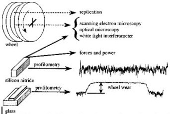
Fig. 1-Schematic illustration of experimental method

Periodic measurements were made of the radial wheel wear. For this, a grinding pass was taken on a glass specimen somewhat wider than the grinding wheel as illustrated in Fig. 1. Since the ceramic workpiece specimen was narrower than the wheel width, that portion of the wheel not used for grinding provided a reference surface from which to measure the wear on the active portion of the wheel width. A profilometer stylus trace (Mahr Corp.—Perthometer Concept) was made across the grinding track on the glass specimen to measure the wear depth. For each specimen, three measurements were taken at different places and averaged.
In order to observe the progressive change in wheel topography, four replicas were taken using cellulose tape at marked locations around the wheel surface after completing each ceramic specimen. The replicated samples were examined using both optical and scanning electron microscopy (SEM). Furthermore, a high-standoff optical microscope and SEM were used to study the wheel surface after completing each wheel life test. SEM observations were also made of ground surfaces after various grinding times. The workpiece surface roughness was measured using both a stylus device (Mahr Corp.—Perthometer Concept) and an optical device (WYKO Corp.—Rollscope).
References
[1] Klocke, F., Brinksmeier, E., Evans, C. J., Howes, T., Inasaki, I., Tonshoff, H. K., Webster, J. A., and Stuff, D., 1997, ‘‘High Speed Grinding—Fundamentals and State of the Art in Europe, Japan and the USA,’’ Ann. CIRP, 46, No. 2, pp. 715–724.
[2] Inoue, K., Sakai, Y., Ono, K., and Watanabe, Y., 1994, ‘‘Super High Speed Grinding for Ceramics with Vitrified Diamond Wheel,’’ Int. J. Jpn. Soc. Precis. Eng., 28, pp. 344–345.
[3] Kovach, J. A., Blau, P., Malkin, S., Srinivasan, S., Bandyopadhyay, B., and Ziegler, K. R., 1993, ‘‘A Feasibility Investigation of High Speed, Low Damage Grinding for Advanced Ceramics,’’ SME 5th International Grinding Conference, SME, Vol. I.
[4] Kovach, J. A., Laurich, M. A., Malkin, S., and Zhu, B., 1994, ‘‘High-Speed, Low-Damage Grinding of Silicon Nitride,’’ Proceedings of the Annual Auto-motive Technology Development Contractors’ Coordination Meeting, October, Dearborn, Michigan, pp. 411–421.
[5] Maksoud, T. M. A., and Mokbel, A. A., 1995, ‘‘Very High Infeed Effects on the Grinding of Advanced Ceramic Materials,’’ Al-Azhar Engineering 4th International Conference, December 16–19, Cairo, Egypt.
[6] Malkin, S., 1989, Grinding Technology: Theory and Application of Machining with Abrasives, John Wiley & Sons, New York (reprinted by SME, Dearborn, MI.)
[7] Ukai, N., 1993, ‘‘Super High Speed Grinding with Vitrified CBN Wheels,’’ SME 5th International Grinding Conference, SME, Vol. I.
[8] Konig, W., and Ferlemann, F., 1990, ‘‘CBN Schleifsceiben fur 500 m/s Schnittgesschwindigkeitt,’’ Ind. Diam. Rundschau, 24, pp. 242–251.
[9] Tonshoff, H. K., Karpuschewski, B., Mandrysch, T., and Inasaki, I., 1998, ‘‘Grinding Process Achievements and Their Consequences on Machine Tools Challenges and Opportunities,’’ Ann. CIRP, 47, No. 2, pp. 651–668.
[10] Hwang, T. W., Evans, C. J., and Malkin, S., submitted, ‘‘High Speed Grinding of Silicon Nitride with Electroplated Diamond Wheels, Part 2: Wheel Topography and Grinding Mechanisms,’’ ASME J. Manuf. Sci. Eng., 122, pp. 42–50.
[11] Hwang, T. W., 1997, ‘‘Grinding Energy and Mechanisms for Ceramics,’’Ph.D. Thesis, University of Massachusetts.

http://link.aip.org/link/?JMSEFK/122/32/1


  Â ýëåêòðîííóþ áèáëèîòåêó 

| Ãëàâíàÿ ñòðàíèöà ÄîíÍÒÓ| Ñòðàíèöà ìàãèñòðîâ ÄîíÍÒÓ|