|
Review of existent researches
There are the folldwing groups of roller tables according to their purposes: working , to serves the technological machines; transport to feed the rolled metal to the technological machines; special, to transport billets, and do a number of other operations. They can be annealing, shaking, movable, packing and so on.
Working roller tables are the most loaded machineries with large number of working hours, (> 1000)a hour, shock application of forces, multichain systems with a general reason.
On a fig. 1.1 [1], a scheme of a working roller table with the small step of rollers 4, is given to feed short bars (billets). The rollers have a general drive with a transmission shaft and conical transmissions 2, which are mounted in one case with lubricating bath for a gear box 1.
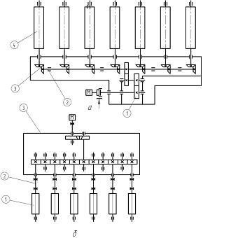
Fig. 1.1 – Sheme of a roller tablewith a group drive with the conical (б) and cylinder (б) transmissions
Another kinematic scheme of a working roller table is characteristic for pressing , thick sheet and billet rolling mill (fig. 1.1b) [1].
The rotation of rollers takes place through a distributive gear box with the cylinder transmissions. Torque moment from a gear box 3, is passed by a roller 1 through the transmission shafts 2 with tooth-type coupling or Gouca hinges .
In the given course project a working roller table of cage 950 in the workshop of a primary mill is dealt with; the kinematics scheme of which is given on fig. 1.2 [1]. Roller table consists of 11 rollers. First three rollers, set before a cage, have an individual drive from the direct current engines D814 U2. Next 8 rollers have a group drive from two engines D814 U2, through a distributing gear. The low gear of a reducing gear is divided and is a helical one. The output shafts of a reducing gear are connected with rollers by means of tooth-type couplings.
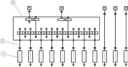
Fig. 1.2. – Scheme of a working roller table cage 950
Rollers fulfil the function of transporting a bar to the working cage.
In the process of a bar moving rollers undergo pressure from the side of a bar, and pass this pressure to the bearings.
While operation a working roller table can work in one of the following modes of operations:
1) ingof transporting and rolling;
2) ingot turning on a roller table;
3) idling;
4) reception of a rolled ingot out of a cage.
Each of the above listed modes is characterized by its own modes of loading of a roller table components.
Rollers are the working organ of a roller table, therefore loading acting on a roller table are considered in relation to rollers.
Loading on all the other details and knots of a roller table ( rollers bearing, gears and tooth gear of a distributing reducing gear, reducing gear bearing, reducing gear shafts and coupling) can be received according to the set loading on rollers.
Transporting of ingots and rollings is the basic mode of operations of a working roller table (to the related time taken). For this mode loading on rollers will be determined by ingot weight and its length.
Loading on one roller is inversely proportional to the number of rollers which are simultaneously in contact with rolled metal. After each passage in a rolling cage the ingot weight is distributed among bigger number of rollers, loading on rollers and torque moment transmitted to the components of a roller table drive accordingly reduce.
It is considered that the ingot weignt while transporting is perceived by 3 rollers (fig. 2.1a) [1].
While transporting of a rolled ingot, when its length exceeds 2 steps between rollers, loading on one roller can be defined as the rolled ingot mass, related to the number of rollers which a rolled ingot lies on (fig. 2.1b) [1]. But in practice some number of rollers do not contact directly a rolled ingot, due to its unevenness, it is assumed, that 70% of all rollers are in contact with a rolled ingot.
During idle work of a roller table rollers undergo loading only from their own gravity force.
In the modes of a roller table turning (fig. 2.2a) [1] the dynamic loading operates on rollers .
Besides that dynamic loading acts on the rollers of a roller table from a cage. There are two possible variants of a rolled ingot leaving a cage (fig. 2.2б, and 2.3) [1].
While rolling with lower pressure is ring rolling given on rollers from above. In the case when a ring rolling is bent on leaving a cage it abuts against a roller (ris.2.3) [1], as a result slip of a rollid ingot is possible.
Loadings acting on the roller table rollers while transporting of a ring rolling and its turning are considered in master’s degree work.
Fig. 2.1. – Presenting solid in wolfs
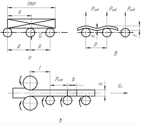
Fig. 2.2. – Schemes of a roller table loading while transporting of: a) initial ingot; b) – rolling; c) – on leaving the rolls.
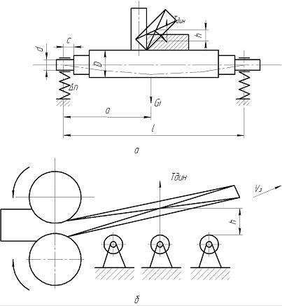
Fig. 2.3. – Schemesof dynamic forces action on a roller: a) – while ingot turning over; b)– while rolling with lower pressure
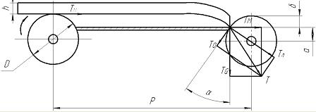
Fig. 2.4. – Schemes of forces action when rolling comes into contact with a roller.
Own Results
ANALYSIS OF A WORKING ROLLER TABLE FAILURES, REASON OF FAILURES
Having analysed a register, 39 failure reasons have been selected:
1) wear of rolling bearing;
2) wear of rolling of p/s;
3) wear of rolling bearing;
4) destruction of rolling bearing of h/s;
5) destruction of rolling bearing of p/s;
6) destruction of bearing;
7) lubrication shortage POUHS;
8) lubrication shortage POUPS;
9) lubrication shortage;
10) loosening a threaded joint of h/s;
11) loosening a threaded joint of p/s;
12) loosening a threaded joint;
13) revision POUHS;
14) revision POUPS;
15) revision;
16) wear of rolling bearing of a distributing reducing gear;
17) loosening of threaded joint r.r.;
18) destruction of threaded joint r.r.;
19) destruction of a rolling bearing r.r.;
20) wear down of a gear;
21) destruction of end-tail;
22) lubriation shortage;
23) dislocation of bearing rings;
24) destruction of pillows;
25) wear of gaskets;
26) wear of fit place;
27) revision r.r.;
28) wear roller wear;
29) wear of fit place;
30) destruction of a tooth rim;
31) loosening a threaded joint;
32) lubrication shortage;
33) wear of tooth type coupling;
34) round of tooth type coupling;
35) revision;
36) friction is out of adjustment;
37) destruction of a pillow;
38) crack;
39) reason unknown.
On fig. 3.1 we can see the resulted histogram of destributing the number of quantity of refusals according to their reasons.
It is visible from the histogram on fig. 3.1, that the main reasons of defects are: 7) Shortage of lubrication in a bearing knot from an idle side; 8) Shortage of lubrication in a bearing knot from a drive side; 12) loosening of a threaded joing; 15) Revision; 31) loosening of a threaded joint; 32) Lubrication shortage.
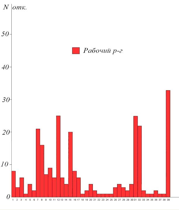
Fig. 3.1. – «Refusals – reason of refusals» of a working roller table cage 950
On fig. 3.2 distributing of refusals on the knots of a roller table is shown . It is visible from a histogram, that the great number of refusals arises up in a bearing knot from an idle side, in tooth type couplings, and in a distributing reducing gear.
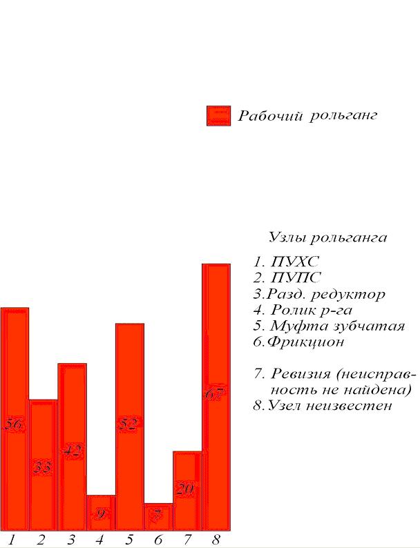
Fig. 3.2. – «Refusals – knot» of a working roller table cage 950
REFUSAL – TIME
Analysing the refusal – time we come to the conclusion, that during the period from 1998г. to 1999 and from 2000 to 2001 there were a plenty of refusals, but then there was the continuous reduction of refusals. It was due to the observance of rules of exploitation and rules of roller table service by technical repair personnel.
On average breakages during a period from 1998 to 1999 were: destruction of bearing of a bearing knot from the drive side 0,5 months; wearing of bearing of a bearing knot from the drive side 1,3-months; wearing of roller 0,5-months; loosening a threaded joint 0,5 masses-months; wearing of bearing in the distributing reducing gear 1,5-months; wearing of bearing of a bearing knot from an idle side.
On average breakages from 2000 to 2001 were: destruction of bearing of bearing knot from the drive side 1,75-months; wearing of bearing of bearing knot from a drive side 1-month.; wearing of fitting place of roller 1-months.; wearing of roller 1-month.; wearing 1-month.; loosening a threaded joint 0,5-months.; wearing of in a distributing reducing gear 1-months.; wearing of bearing in a distributing reducing gear 1-month.; wearing of bearing in the bearing knot in an idle side 2-months.; destruction in the bearing knot of idle side 1 month.
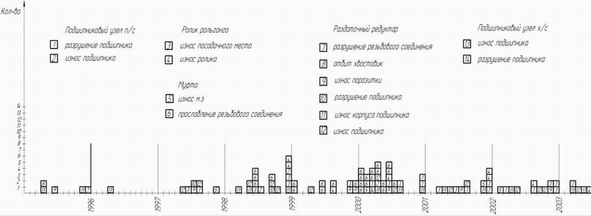
Fig. 3.3. – «Refusals - time» of working of roller table cage 950
ANALYSIS OF HISTOGRAMS
Histogram «Refusals - time»
Analysing a histogram «Refusals - time» received as a result of the data processing of a register, we can see that during the periods from 1998 to 1999 and from 2000 to 2001 year there were a plenty of refusals. While analysing histograms main attention was paid to exactly this interval of time, during this period a register was conducted with high quality.
It is necessary to pay, as much as possible attention to the question of faultlessnees and longevity of a working roller table, as the quality of products and productivity of a workshop depend on it.
Histograms «Refusal – knot» and «Refusals – reason of refusals»
More often we can see the refusal (repair action) of knots of a working roller table. It is connected with loading a roller table perceives in the process of the work, which undergoes the most loading.
Analysing the received histograms, we see:
Threaded joints on most knots of roller table are weak points.
Timely feed of lubrication is a very important factor of normal work of knots of roller table. Interruptions with the feed of lubrication can lead to growth of wearing the knots.
The large number of refusals (repair actions) happened on a tooth type coupling. It is necessary to pay attention to this knot.
Often bearing of rolling are out of order, particularly bearing knots from an idle side fail more frequent, than from a drive side.
A plenty of the analysed refusals (repair actions) can not be subjected to clear classification. It is due to the fact there are simply no set norms of conducting the register and everybody filled it in his own way.
CALCULATION OF A STRESSFUL STATE OF A ROLLER TABLE IN ANSYS PACKAGE
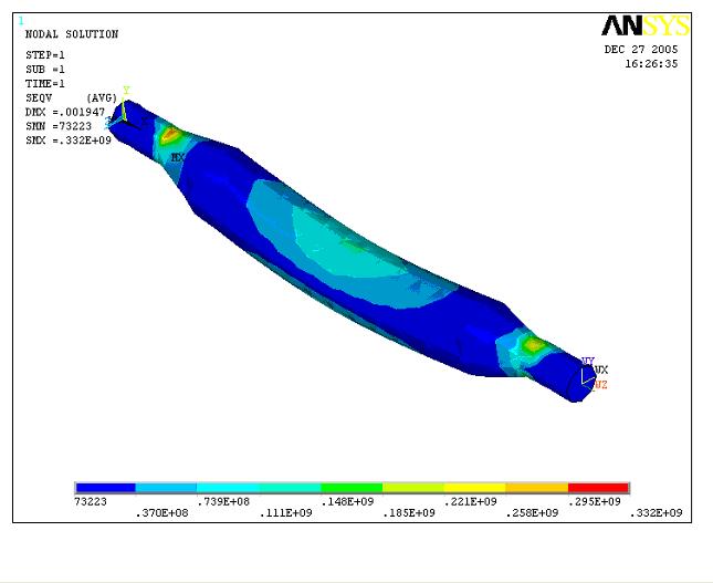
Fig. 4.1 – Distribution of equivalent tensions in a roller
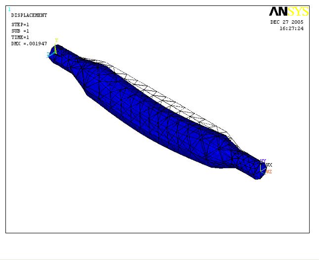
Fig. 4.2 – Deformation of a roller
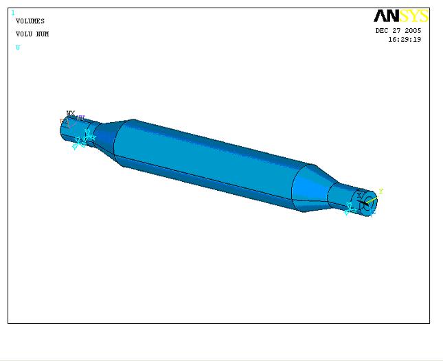
Fig. 4.3 – The Geometrical model of a roller
To study the distribution of tension arising up in the body of a roller at the turning of a bar, the simulation a ANSYS package was made.
For this purpose on the basis of a roller drawing the geometrical model was created, see fig 4.3, and the properties of roller were set: material – module of resiliency was 2*10^5 MПа and Pouassona coefficient was m=0.3. Further a model was broken into eventual elements. A tetraid with 10 knots was used as an element. Surfaces on with the bearing, were fixed, and as the external loading the force
was exerted which was equal to dynamic force arising while turning a bar with the cross section 645x660 and equalt 2MH, see addition 2, force was exerted as concentrated on the center of roller.
As a result deformations and distributed tensions in the roller, see fig. 4.1, and the distributed tensions , see fig. 4.2, were received.
As we can see from pictures maximal deformation was 2mm in the point of applying the force, and equivalent tensions were calculated on the 3th theory of durability on the center of a barrel of 110 MT, and maximal 330 MT. Maximal tension arises up in transition from a pin to a conical part of a roller.
The received tensions do not exceed the legitimate values for roller material.

|
|
List of the used literature
1. Розрахунок машин і механізмів прокатних цехів: Ф.К. Іванченко, В.М. Гребеник, В.І. Ширяєв.-К.: Вища шк., 1995.-455с.
2. Королёв А.А. Конструкция и расчёт машин и механизмов прокатніх станов: Учеб. Пособие для вузов.-2-е изд., перераб. и доп. – М.; „Металлургия”. 1985. 376с.
3. Марутов В.А. и Павловский С.А. Гидроцилиндры. Конструкция и расчет. – М "Машиностроение", 1966. – 315 с.
4. Производство блюмов, слябов и заготовок из углеродистых и легированных сталей в обжимном цехе. Технологическая инструкция. ТИ – 234 – П.03.01 – 95. Донецкий металлургический завод.: – Донецк, 1995. – 225 с.
5. Целиков А.И., Полухин П.И., Гребеник В.М. и др. Машины и агрегаты металлургических заводов. Том 3. Машины и агрегаты для производства и отделки проката. – М.: Металлургия, 1988. – 576 с.
6. Королев А.А. Конструкция и расчет машин и механизмов прокатных станов. Учеб. пособие для вузов. – М.: "Металлургия". 1985. – 367 с.
7. Анурьев В.И. Справочник конструктора-машиностроителя: В 3-х т. Т.1. – М.: Машиностроение, 1982. – 736 с.
|

