ADVANCED SPECTRAL ANALYSIS
Pete Bechard. PdMA Corporation
CURRENT SIGNATURE ANALYSIS
As industries continue to look for new methods of identifying and predicting equipment failures, manufacturers of predictive maintenance equipment are developing new tools to add to their arsenal of available technologies. Newly developed methods of extracting information from the line current supplied to a motor, have uncovered information on both the electrical and mechanical health of the equipment. Not just the power supply and motor, but now tracking and trending of information deep into the load and shaft line components can be done through the line current as well. This article discusses the fundamentals of these new current demodulation methods and shows how they are being used to identify both electrical and mechanical anomalies existing in plants today. It also discusses how using this new feature helps bridge the communication barrier between the mechanical and electrical departments relating to vibration and electrical power analysis.
Since 1985, Current Signature Analysis (CSA) has been growing as a preferred predictive maintenance tool to identify damaged rotors and air gap eccentricity in induction motors. CSA is based on the observation that variances in the stator-rotor air gap are reflected back into the motor’s current signature through the air gap flux affecting the counter electromotive force (CEMF). These changes in CEMF then modulate the running current turning an induction motor into an efficient transducer. By performing a Fast Fourier Transform (FFT) on motor current the power cables can act as permanently installed test leads for predictive maintenance applications.
A FFT is a mathematical operation that extracts the frequency information from a time domain signal and transforms it to the frequency domain. The frequency domain is a graph of the amplitude of a signal at a given frequency. In the frequency domain, the height of the peak represents the amplitude of the signal. Figure 1 shows the relationship between the time domain (t), the frequency domain (f), and amplitude (A).
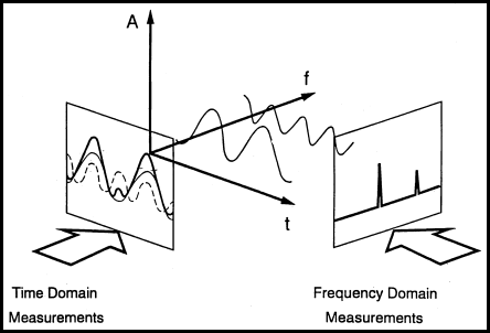
Figure 1: Relationship Between Time, Frequency, and Amplitude
ROTOR BAR DAMAGE
In CSA, the pole pass frequency (FP) appears as sidebands surrounding the line frequency (FL) after performing a FFT on a captured signal. The synchronous magnetic pattern of the stator rotates faster than the rotor cage. This implies that any given rotor bar is passed by all of the magnetic poles in one rotation of the slip frequency. The rate at which this occurs is termed the FP. Often in vibration analysis the term for this is called the motor pole passing frequency (PPF). (PPF = motor slip X number of poles). The difference in amplitude between the FL and the FP is an indication of rotor health. Empirical research has shown that a difference of over 54 dB indicates a healthy rotor while less than 45 dB indicates a degraded (i.e., high resistance joints, cracked or broken bars) condition exists in the rotor. An example of CSA showing a damaged rotor is shown in Figure 2.
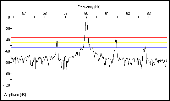
Figure 2: Spectrum of a Motor With Damaged Rotor
STATOR-ROTOR AIR GAP ECCENTRICITY
Air Gap Eccentricity describes the measurable distance between the stator and rotor within the motor. Manufacturers take great care to ensure that air gap eccentricity is kept to a minimum. Typical maximum levels for large induction motors are between 5 to 10%. There are two types of eccentricity, static and dynamic. Static eccentricity is when the minimum air gap is fixed in space such as when the rotor is misaligned along the stator bore. Dynamic eccentricity describes the condition when the minimum air gap revolves with the rotor. A bowed rotor results in a dynamic eccentricity. If the distance between the length of the stator bore and rotor is not equal throughout the entire circumference, varying magnetic flux within the air gap creates imbalances in the current flow, which can be identified in the current spectrum. The effect of this condition is seen as multiple sidebands of odd harmonics of the line frequency powering the motor. These sidebands will develop around the eccentricity frequency (FECC).
FECC = (# of rotor bars) X (RPM/60)
Figure 3 is CSA results from a motor operating with an excessive air gap eccentricity. The more severe the eccentricity becomes, the amplitude of the peaks will increase.
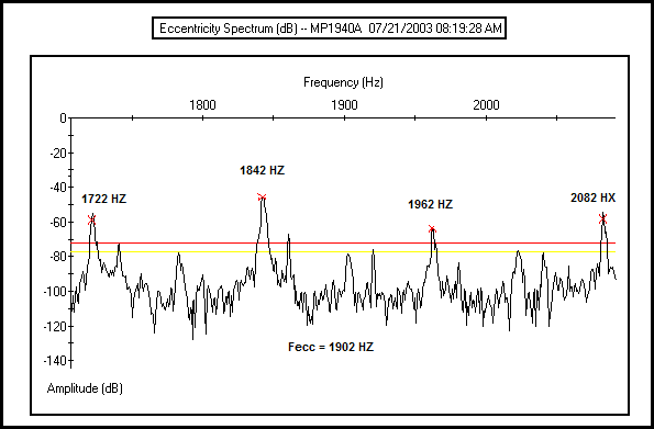
Figure 3: Current Spectrum of a Motor With Air Gap Eccentricity
MECHANICAL COMPONENTS
Developing the ability to condition and filter the current signal passing through a motor’s windings expands CSA to detect load variations, which are related to mechanical processes. The term used for this process is demodulation. Demodulation is the process by which a signal is recovered from a modulated carrier. Modulation is the process by which some characteristic of a carrier (the 60 Hz applied to the motor) is varied (the rotor flux creating CEMF) in accordance with a modulating wave. Simply put, the load variations that repeat at a constant frequency are reflected into the stator currents through the motor’s CEMF. Remove the 60 Hz signal and these frequencies become apparent. The removal of the 60 Hz portion of the signal (demodulation of the carrier frequency) reveals repetitive load variations for analysis.
PdMA is currently using amplitude demodulation of the current signal to greatly expand the capabilities of the EMAX tester. Using a software-driven mode of demodulation to remove the 60 Hz signal, the ability to detect motor speed, pole-pass, mechanical pass-through, and reflected frequencies is greatly enhanced. These mechanical and reflected frequencies are related to load variances from items such as belts, gears, pumps, fans, and other mechanical components. To evaluate the magnitude of these frequencies, a FFT is performed on the demodulated signal resulting in a spectrum for analysis. Without the demodulation, many of these load related frequencies are buried in the signal-to-noise ratio of the captured data.
The following examples of using motor current demodulation to evaluate equipment condition are from a large public aquarium. The data was gathered using PdMA Corporation’s MCEMAX motor tester with Advance Spectral Analysis (ASA). When using demodulated current analysis to monitor mechanical components it is import to establish a baseline when the equipment is known to be in satisfactory condition. After identifying frequencies related to specific components and conditions, any significant increase in amplitude should be investigated.
Rotor Unbalance/Misalignment
The number of poles determines the speed of an AC Induction motor. A 2-pole A C Induction motor being powered by a 60 Hz line frequency runs at a speed slightly lower than 3600 RPM or 60 cycles per second (Hz). A 4-pole motor runs at a speed less than 1800 RPM or 30 Hz and so on. By utilizing current demodulation, the speed of the motor can be identified by a peak in the spectrum and monitored for changes in amplitude. A properly balanced and aligned motor has a frequency peak related to its speed that is barely visible. When the motor is out of balance or misaligned, this peak’s amplitude will increase. As the condition increases in severity, then multiples of the speed frequency develop in the demodulated current spectrum. Figures 4 and 5 demonstrate the change in amplitude of the running speed and 2 X running speed during a precision alignment of a pump and motor.
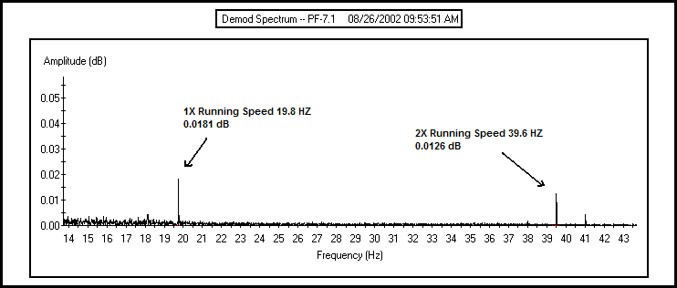
Figure 4: Demodulated Current Spectrum Prior Alignment
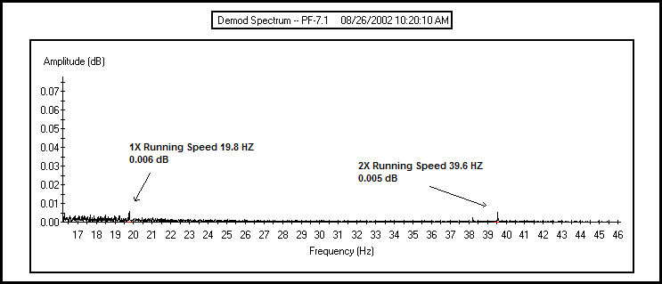
Figure 5: Current Demodulation Spectrum After Alignment
Belts
When transmitting power to the load via a belt attached to the motor changes in alignment can be evaluated using the demodulated current spectrum. Evaluation of the current spectrum is similar to alignment in that increases in the amplitude of the belt frequency and the development of multiples of the belt frequency indicate a problem. To calculate belt frequency requires the operator to know the diameter of the pulley mounted on the motor and the length of the belt.
Belt Frequency = 3.142 (D/L) X (RPM/60)
D is diameter of the motor mounted pulley
L is the length of the belt
RPM is the motor speed
In the following example you can see the dramatic change in the demodulated current spectrum after proper tensioning and alignment was performed on a drive belt. In Figure 6, the belt frequency is 8.188 Hz and there are elevated peaks at multiples of the belt frequency. Notice in Figure 7 how the multiples of the belt frequency have disappeared and how much lower the amplitude of the belt frequency is after the work was completed. These frequencies can now be easily monitored detecting possible problems developing in the belt drive of this system.
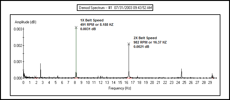
Figure 6: Demodulated Current Spectrum Prior Belt Alignment
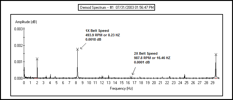
Figure 7: Current Demodulation Spectrum After Belt Alignment
Fans/Centrifugal Pumps
Fan blades and centrifugal pump vane frequencies can be monitored in a demodulated current spectrum at a frequency that is equal to the number of blades (or vanes) times the FP. Increasing amplitude at this frequency as well as a possible increase at the motor speed frequency peak is an indication of possible blade or pump vane damage. After initial installation or verification that the pump or fan is in satisfactory condition, identify the vane frequency and record the amplitude of the peak. Now with baseline amplitude for the equipment established, the demodulated current spectrum is used as a simple and efficient method to monitor the equipment.
Figures 9 and 10 are a comparison between two identical horizontal pumps. Figure 9 is typical for this application with the pump vane frequency amplitude of 0.027 dB. In Figure 10, pump PF-8.6A pump vane frequency amplitude is 0.046 dB; nearly double that of all the other identical equipment platforms. Additional testing was performed on pump PF-8.6A and it is currently scheduled for inspection of the impellor.
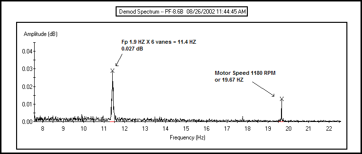
Figure 8: Typical Current Demodulation Spectrum for Several Identical Pumps
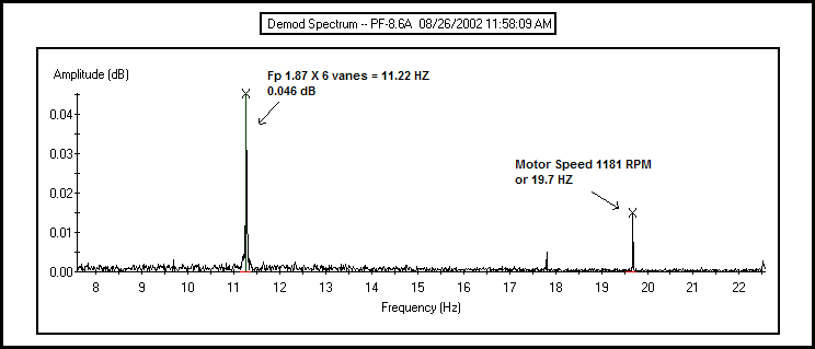
Figure 9: Current Demodulation Spectrum of Pump with Suspected Impellor Damage
Loose Motor Foundation
Loose foundation bolts, soft foot, or a distorted bedplate can lead to air gap eccentricity in a motor. Over time a motor that is improperly mounted can develop a distorted frame due to thermal expansion and contraction as the motor heats up and cools down. Additionally a loose motor foundation will make it all but impossible to maintain correct alignment with the powered load. Loose motor foundation can be detected in a demodulated current spectrum by an elevated peak at half of the motor’s running frequency. If the amplitude of this peak is increasing over time you should investigate the condition of the motor’s foundation, mounting bolts, and shims.
Figure 10 is a demodulated current spectrum from an induction motor powering a pump with possible loose mounting bolts. When the motor is properly mounted to its foundation this peak is usually not even visible. Having identified this peak in a demodulated current spectrum indicates that a thorough inspection of the motor’s foundation is warranted. If the condition worsens the amplitude of the frequency peak will increase.
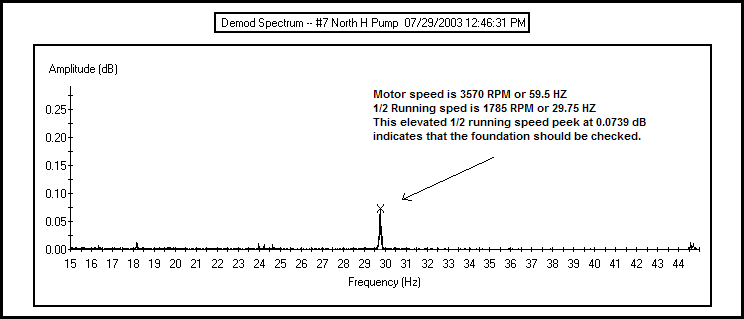
Figure 10: Current Demodulation Spectrum of Motor/Pump With Loose Foundation
CONCLUSION
Analyzing a motor’s current can effectively improve the efficiency and effectiveness of any maintenance organization. As more empirical data from the field is gathered it is becoming clearer that mechanical components can be monitored through the use of a motor’s power leads. Using current analysis in conjunction with other predictive maintenance equipment can lead to significant savings in cost by reducing the man-hours spent on collecting data. Current analysis can be used to monitor belts, gears, alignment, and other mechanical components. Use these new features in current analysis to bridge the communication barrier between the mechanical and electrical departments relating to vibration and electrical analysis.
References
- Introduction to Machine Vibration. Glenn D. White. 1997 DLI Engineering Corporation
- Motor Bearing Damage Detection Using Stator Current Monitoring. Randy R. Schoen, Farrukh Kamram, Thomas G. Habetler and Robert G Bartheld. IEEE Transactions on Industry Applications, Vol. 31, No. 6 November/December 1995
- Rolling Element and Fluid Film Bearing Diagnostics Using Enveloping Methods. Anton Azovtsev and Alexei Barkov. VibroAcoustical Systems and Technologies, Inc.
- A Guide to the Interpretation of Frequency and Time Domain Spectrums.Robert M. Jones, Ph.D. SKF Condition Monitoring Revision 1, 19 February 1993
- A Review of On-Line Condition Monitoring Techniques for Three-Phase Squirrel-Cage Induction Motors Past present and Future. W. T. Thomson, Senior Member IEEE. The Robert Gordon University, Schoolhill, Aberdeen, Scotland