Table of contents
At the present time, the radio is one of the dominating communication media. Such
situation is caused by a number of factors, among them are the high bandwidth, flexibility,
cheap maintenance costs and relative simplicity of radio channel routing. However, there is
also a problem of high radio frequency range commitment, and, as a result, significant
interference issues of a quite unpredictable kind. A possibility of switching to other,
'clean' channels, could be the solution to this problem.
Furthermore, there are other purpose radio systems, that utilize the same frequency range
as the communication ones. Providing solutions for their mutual functioning is one of
the most important tasks for today's communications engineering. There is also a problem
of detecting any spurious radiation that can cause noise and interference, and in that
case, it is necessary to have an estimation of spectra in a wide frequency range.
The requirements for radio transmission quality become more and more strict
every day. In such conditions it is necessary to provide the lowest noise level possible,
without degradation of other features.
Low-noise frequency synthesizers are used in main and zone radio relay
broadband lines (TV, multichannel telephony), panoramic receivers and spectrum analyzers,
measurement devices, as well as any other systems that require fast and accurate switching
in a wide frequency range. [2, p.191]
The cardinal problem of frequency synthesizer design and construction
is the inevitable output noise rise when widening the frequency range. Existing solutions
include increasing Q of the VCO, reference oscillator, precise PLL calculation, or using
multiple VCO's for different frequency sub-ranges.[4].
- design of high precision frequency synthesizer based on general purpose elements
- research of remnant noise issues and developing the ways to eliminate them
- developing of optimal computer modelling methods
Intended practical result: working prototype of programmable
PLL frequency synthesizer
Goals and objectives
The goal of the research is widening the PLL synthesizers frequency range, that will make
possible to employ the sequential mode of functioning for radio communications, diagnostics and
control systems.
The objectives are:
- Research the existing solutions and analyze them for the possibility of
improvement
- Design an optimal PLL frequency synthesizer structure
- Calculate the synthesizer element parameters
- Build a computer model based on the designed structure and its parameters.
Run the simulation and evaluate the results.
- Desing the synthesizer electrical circuit and PCB
- Build the working prototype and proceed with experimental research
The research on PLL systems, as well as the other fundamental communications issues
is led by professor Alexander G. Vorontsov
Searching DonNTU masters site yielded only one reasonable result:
"Development of
signal spectral evaluation methods for telecommunication systems" by Oleg V. Khmelevoy.
Most of the research concerning PLL synthesizers is concentrated around the FM
radio and GSM frequency ranges. There is no apparent interest in or any articles
on UHF range.
A number of well-known researchers work in this area, among them is
Michael Perrott of MIT.
Moreover, there are numerous publications concerning the topic in question, but most
of them are of commercial/advertising kind, and provide little to no useful
scientific information.
Panoramic devices (such as receivers and spectrum analysers) allow to receive all the
radiation in a specific frequency range, or to analyse the spectrum of any radiation. Like
the panoramic receiving, spectrum analysis is based on identification of difference between carrier
frequency and spectral components frequencies of received signal.
Devices designed for monitoring a large number of radiation sources in a wide frequency range,
are called panoramic receivers. Devices for analysing the spectra of radiation or any other processes,
are called spectrum analysers.
There are two modes of frequency analysis: parallel and sequential. There are also a number
of their combinations that unite the advantages of both while partially evading their drawbacks.
The parallel frequency analysis is based on simultaneous detection of all the spectral components
in the specified frequency range called swath. It is performed using a large number of
filters with biased frequency bands. All the filters are sumultaneously influenced by the received signal
or signals.
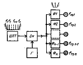
Fig.1. Parallel panoramic receiver structure
The means of operation for parallel panoramic receiver are the following:
at the input, the signal passes the broadband preselector (bandwidth of the preselector
is equal to swath). This part of the circuit is called broadband section. It amplifies
the analysed signal to the level required by the following analyser elements. In the mixer,
the spectrum is down converted to an intermediate frequency without losing component amplitude
ratios and frequency distribution. Thus, the shape of analysed spectrum remains the same.
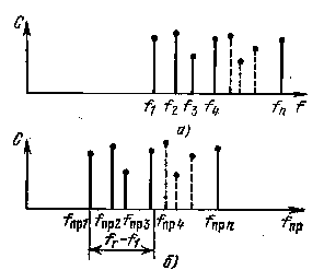
Fig.2. Spectrum down conversion
Here it is necessary to take into consideration that mixer properties and mode of operation
should not cause interference within analysed frequency band.
A set of narrowband filters is used to analyse the downconverted spectrum. Their resonant
frequencies are evenly distributed within analysed frequency range. Every filter responds to
the frequency component that is within its band. A conclusion can be made on the analysed spectrum
structure by inspecting the number and distribution of excited filters. In this case, the precision
is limited by the bandwidth of every filter. Therefore, to increase precision given the same frequency
range, it is necessary to increase the quantity of filters, which becomes the main drawback
for the parallel mode.
Another type of panoramic receiver is sequential. It is based on sequential detection of frequency
components in a specified swath. This type of panoramic devices became quite widespread due to its
simplicity. It is only necessary to have one narrowband filter to build such device.
There are sequential receivers with resonator tuning:
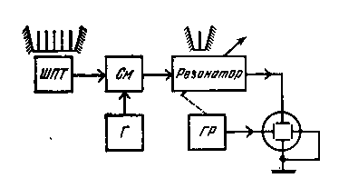
Fig.3. Structure of panoramic receiver with resonator tuning
…and with spectrum shifting:
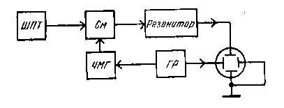
Fig.4. Structure of panoramic receiver with spectrum shifting.
Sequential analysers with resonator tuning are usually quite difficult to implement in
circuit. While simple resonators do not provide the required resolution, more precise
and complicated systems are difficult to tune within wide range, because their
gain frequency characteristic becomes uneven. That's why resonator tuning is used only
when it is impossible to implement spectrum shifting, but frequency resolution requirements
can be lowered.
Therefore, panoramic devices with moderate bandwidth usually employ shifted spectrum
frequency analysis.
To shift the spectrum along the frequency axis, the output from the broadband section (which
is, in fact, the analysed spectrum) and the voltage from linear frequency-modulated oscillator
are fed to a mixer. Thus, the frequency components of the analysed spectrum, are sequentially transformed
into the resonant frequency of the filter, and the spectrum shifts relatively to this frequency, according
to the law of oscillator frequency variation. It is important that the filter gain and frequency
response are matched to this law.
Oscillator frequency can be changed manually or automatically. Manual tuning is used for
thorough inspection of radiation characteristics in relatively narrow swath.
Sequential panoramic devices suffer from transients caused by switching of the filter
or variation of frequency. These transients cause limitations to switching and, as
a result, analysis speed. Also, sequential analysis of rapidly variating or very
brief processes is possible only provided their periodicity is proportionate (or even higher)
to the periodicity of sweep scanning.
Let's examine shifted spectrum receiver structure more thoroughly.
The sweep generator and frequency-modulated oscillator together are, in fact, a chirp generator.
The idea of using chirp signal is based on the following. Multichannel processing is needed
to detect a signal with unknown frequency bias. This means that every channel should have an
optimal detector in it (a matched filter etc.), that detects specific bias. On the other hand,
using chirp signal allows for only one channel, since there will always be a response on the output
of matched filter, with some time delay and amplitude loss.
A chirp signal is a radio pulse with frequency linearily increasing or decreasing
from its beginning to the end. The momentary frequency of such frequency is calculated
using the following expression: ω(t)=ω0+kt, where ω0 is
the starting signal frequency, and k — linear time variation quotient.
The field of application for chirp signals is rather wide and includes:
- 1. Target detection and evaluation
- Today's radars widely use chirp signals for target detection, since
using them do not require great number of Doppler channels. This is due to
the comb-shaped signal ambiguity function, that greatly mitigates even significant
Doppler distortion influence on output signal amplitude.
- 2. Space object recognition
- 3. Radioaltimeters
- 4. Physical measurements
- 5. Communications
Due to the great variety of requirements to chirp generator parameters and
precision, a number of different devices are used for their implementation, like
passive ones with dispersive delay lines, controlled autogenerators, or high precision
synthesizers with multiple control systems.
PLL frequencey synthesizers are widely used in all areas of today's radio technics.
Typical PLL synthesizers can generate a sine signal with several GHz frequency,
sampling rate over 10MHz, synchronous to the reference frequency, and with equal
phase stability. Morever, PLL synthesizers have a high spectral purity that is
required for high resolution radar equipment. The main drawbacks of such synthesizers
are the limited switching speed, limited frequency range, and the complexity of construction
and tuning.
The VCO,
is a determinant element of PLL synthesizer. It should work in the whole
frequency range, while producing low noise and spurs. To keep the loop stable,
the VCO must have a low frequency drift. Designing such an oscillator is rather
complex, particularly for frequencies over 100 MHz, even with specialized
VCO IC's available. These oscillators also require thorough and precise tuning.
Another pitfall in PLL synthesizer design is the controversy of requirements to
reference frequency value. Lowering this value can help increase the output sample
rate, while increasing settling time. With the development of electronics this problem,
along with many others, was successfuly solved, and today PLL synthesizers are the most
widespread synthesizer type, used in television, radio and computers. However, the
complexity of calculation and tuning still significantly hampers the evolution of such
systems.
These requirements are essential when designing a PLL synthesizer:
- Frequency range fmax−fmin
- Frequency resolution Δf
- Output power Pout
- Relative output frequency instability Δf/f
- Output noise level relative to noise fluctuation frequency Fш:
 Where Pш(Fш) is
the noise power in 1 Hz bandwith with frequency offset Fn Where Pш(Fш) is
the noise power in 1 Hz bandwith with frequency offset Fn
- Reference spur power

- Switching time τ
Model structure and purpose
An important stage of synthesizer design is modelling its inner processes.
In fact, it is an early experiment stage, and its results can significantly
influence further research and design. In this work, Elanix SystemVue software
is used for modelling.
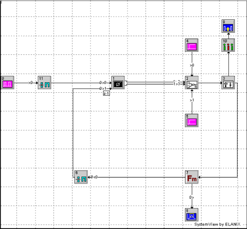
Fig.5. Synthesizer structure
Calculation of loop filter element parameters
In this work, loop filter element parameters are calculated according to
National Semiconductor Application Note 1001 recommendations.
Table 1. Calculation of loop filter element parameters
| Constant values |
Kvco |
20,00E+6 |
Hz/V |
VCO gain. |
Kcp |
5,00E-3 |
А |
Charge Pump gain |
RFopt |
2,00E+9 |
Hz |
VCO frequency when optimized. |
Fref |
500,00E+3 |
Hz |
Reference frequency |
BWhz |
20,00E+3 |
Hz |
Loop bandwidth |
PhMar |
45,0 |
degrees |
Phase margin |
ATTEN |
20,0 |
dB |
Attenuation of reference spurs by the additional RC filter |
Lpf_R3 |
22 000 |
Ohm |
RC-PLL filter series resistor |
|
|
|
|
| Calculated Charge Pump Filter and Low Pass Filter Circuit Values |
N |
4 000 |
|
Divide ratio = (RFopt / Fref) |
|
|
|
|
Ctog |
888,540E-12 |
F |
Capacitor only to ground. (Charge pump) |
Cwsr |
6,13E-9 |
F |
Capacitor with series resistor. (Charge pump)) |
Rwsc |
4,25E+3 |
Ohm |
Resistor with series capacitor. (Charge pump) |
|
|
|
|
Lpf_C3 |
43,41E-12 |
F |
RC-PLL filter capacitor to ground (C3). (RC-PLL filter) |
|
|
|
|
| Calculated Charge Pump Current Source Parameters |
|
|
|
|
Rcp |
1 000 000 |
Ohm |
Charge pump resistor (2 places). (Rcp = 5000/Kcp) |
|
|
|
The resistor after the switches (feeding the charge pump filter) is set to zero ohms. |
|
|
|
|
| Intermediate Calculations |
BWrad |
125 664 |
rad |
Loop bandwidth in Radians = (2 pi * BWhz) |
T1calc |
3,296E-06 |
seconds |
T1 = secPhMar - tanPhMar / BWrad = (1/cosPhMar)
- tanPhMar / BWrad |
T3calc |
9,549E-07 |
seconds |
T3 = sqrt( (10 exp( (ATTEN / 20) - 1) / (2
x PI() x Fref) x 2 ) |
| Calculated loop bandwidth |
BWcalcLT |
4,2511E-06 |
|
BWcalcLT = tanPhMar x (T1calc + T3calc) |
BWcalcLB |
2,1220E-11 |
|
BWcalcLB = ( (T1calc + T3calc) ^ 2 ) + (T1calc
x T3calc) |
BWcalcRT |
2,1220E-11 |
|
BWcalcRT = BWcalcLB |
BWcalcRB |
1,8072E-11 |
|
BWcalcRB = BWcalcLT ^ 2 |
BWcalc |
9,5062E+04 |
Hz |
BWcalc = (BWcalcLT / BWcalcLB) x [ (sqrt(1 +
( BWcalcRT / BWcalcRB) ) - 1] |
T2calc |
2,6030E-05 |
seconds |
T2calc = 1 / [ (BWcalc ^ 2) x (T1calc + T3calc)
] |
| C1 calculations |
CtogLT |
1,0000E+05 |
|
CtogLT = Kcp x Kvco |
CtogLB |
3,6147E+13 |
|
CtogLB = ( BWcalc ^ 2 ) x N |
CtogRT |
7,1232E+00 |
|
CtogRT = ( 1 + (BWcalc ^ 2) x (T2calc ^ 2) ) |
CtogRB |
1,1072E+00 |
|
CtogRB = ( 1 + (BWcalc ^ 2) x (T1calc ^ 2) )
x ( 1 + (BWcalc ^ 2) x (T3calc ^ 2) ) |
Ctog |
8,89E-10 |
F |
Ctog = T1calc / T2calc) x (CtogLT / CtogLB) x sqrt[CtogRT
/ CtogRB] |
| C2 calculations |
Cwsr |
6,13E-9 |
F |
Cwsr = Ctog x ( (T2calc / T1calc) - 1) |
| R2 calculationc |
Rwsc |
4 247,6 |
Ohm |
Rwsc = T2calc / Cwsr |
| C3 calculations |
Lpf_C3 |
43,41E-12 |
Farads |
Lpf_C3 = T3calc / Lpf_R3 |
Model set up using the calculated values:
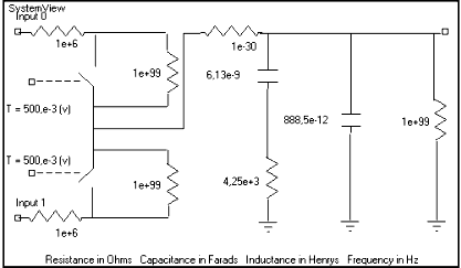
Fig. 6. Charge pump with calculated element parameters
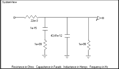
Fig. 7. LPF with calculated element parameters
Most of the simulation software have the possibility of visually building
the model using the basic blocks (oscillators, filters, etc.) However, these
blocks are usually assumed ideal, thus making it impossible to simulate some
particular device. Moreover, calculus of approximations usage, as well as
time window limitation, are also the sources of inaccuracy.
The main problem in output spectrum analysis is so called spectrum leakage [6].
It is caused by an assumption, when calculating FFT, that the sample sequence is
periodically repeating back and forth in time. Additionally, quick frequency alterations
caused by VCO switching transient, significantly influence the output spectrum.
Typically, a weighting function is used to justify these inaccuracies.
A moving average operator can be used to additionally mitigate the influence of
aperiodical components.
Another way of avoiding spurious components in output signal is using a limited time
window to minimize transient influence.
Fig. 8 illustrates the improvements that can be achieved using these methods
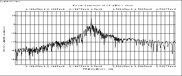
Fig. 8. Output spectrum using various modelling methods.
Having researched the basic features of PLL synthesizer, a conclusion can
be made that this type of synthesizer mostly meets the requirements to chirp
generators. Today's integrated PLL solutions have the possibility of program
control. Thus, by setting the required parameters and varying them according
to the needed law, it is possible to get an output signal with a corresponding
law of variation.
The design of loop filter is by far the most important stage of development,
since it determines the speed-to-noise ratio of the system.
A number of requirements have to be met to obtain the correct results with
computer modelling. They include using an optimal time window, exclusion of aperiodical
component influence, averaging the results. However, it is prudent to take the
features of particular model, such as transient duration and loop filter bandwidth,
into consideration. |