Zabolotnyj I.P., Sazonov V.V.
EMERGENCIES ANALYSIS EXPERT SYSTEM IN ELECTRIC SYSTEMS
Ïåđåâîä Êîđîâêèíîé Å. À.
Source of information:Donetsk national technical university ivđ@ålf.dgtu.dînåtsk. uà
Introduction.
Intellectual systems type new technologies development and the synchronised analogue and discrete information sample realisation, software service increase creates conditions for damages analysis new systems creation.
Damages analysis automation previous campaigns have been connected with fixing devices [1-2], etc., or with data gathering system (SCÀDÀ system) [3], or with digital registrars. Recently the expert systems constructed on neural networks [4-6] are developed for the damage analysis. SCÀDÀ systems had no possibility to calculate a damage place, information analogue signals processing did not become because of their discrete representation insufficiency.
Fixing devices and digital registrars provide a damage place definition on transmission lines emergency operation parameters. Analogue information representation in a digital form with the further processing allows, in the absence of erroneous gaugings, precisely enough to define a short circuit kind on a transmission line, i.e. simple damage. Line static model use in digital registrars influences on short circuit place definition accuracy in real operating network modes. It is necessary to notice, that short circuit kind and a damage place definition on lines is carried out after a while after emergency occurrence.
In [5-6], etc. neural networks (NN) use for an emergency analysis and control with decision reception possibility during process jerk is considered. But, as it is marked in [7], some NN systems integral property is the susceptibility to so-called correlation restrictions. This property essence consists that after optimizing adjustment and training during dithering infusion to one signal, followed expect, that this "spoilt" signal will cause alarm, however every time other faultless signals set cause a false alarm.
On the basis of domestic and foreign authors some works analysis it is possible to classify workings out to following signs:
1. On the purpose: emergency operation control in process jerk (the expert systems constructed on neural networks), the situation analysis directly after an abnormal situation.
2. On the information volume using: the detailed situation description on the basis of information considerable volume; situations sets described conventional in the cause and effect dependences form.
3. By signal kinds: analogue with representation in the digital form and the subsequent processing (digital registrars); telemechanics and other devices discrete signals with use of knowledge bases [8-9].
4. On the analysis depth and objects set: on the basis of simple logic dependences for separate objects , first of all transmission lines, on the basis logic dependences and modes modeling combination, both for separate objects and for an electric network.
1. A general expert system characteristic.
The expert system purpose is the emergencies analysis, report formation within several minutes after failure for relay protection services engineers and OSS. The generalized message to operation personnel contains the information about the damaged element, correctly and incorrectly worked and given up relay protection, automatics, switches devices.
Having received the corresponding information, the personnel can take measures to operative revealed malfunctions elimination: to exclude from the scheme the given up switch, to deduce in check the given up or incorrectly worked RP and automatics devices.
The expert system is intended for work as a part electropower system local objects operational control automated system [10] that provides its functioning on control object uniform information model and integration with other technological problems. In the simplified kind the expert system can be realized in digital registrars. In the present work it is used developed in [8-9] knowledge base part formation method for relay protection work modeling.
Expert system(the centralized type) realization by automated control system on the basis of the integrated raw information gathering from various controllable objects in control point means can be impracticable, even in that case when the necessary information volume is registered, as not always it is possible to carry out necessary information transfer and information synchronization. However, some decisions on damages analysis automation can be carried out on the basis of existing control technologies (fig. 1) by combined type (hierarchical structure) expert system means
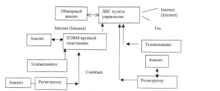
Fig. 1 - Structural the damages analysis scheme
On substation there is a digital registrar which collects data from various devices of connections, including departing lines, and analyzes these data locally. Analysis results as well as raw data are transferred to the central server in control point in general CÎMTRÀDÅ format, including telephone communication lines.
On large substations data from registrars, telemechanics devices are transferred to PC, established on substation where data are processed by automated control system means which software includes also emergencies analysis subroutines in the electric network. PC on substation establishes connection with the control point local computer network, transfers the processed and raw data which are distributed by point "Coordinator" to the local computer network points for technological problems performance, and also data are remained in a database [10].
The corresponding point «Expert system» subroutine automatically classifies and filters reports on the basis of: the damage condition exists, and short circuit switching-off time is satisfactory; the damage condition exists, and short circuit switching-off time is longer, than expected one etc., it processes remained raw information, specifies the made decisions, i.e. makes the extensive analysis. For example, in a case when only two phases currents are known, the current in the third phase will be automatically calculated.
Registrars possibilities allow to analyze the received at failure information and to make the message not in the separate signals form, and in the form of emergencies description reports. For this purpose it is required to get discrete and analogue signals in the digital registrar: basic and reserve protection output relays action; block - spacer or relay contacts, specifying included or disconnected switches condition; output relays of automatics; blocking from repeated inclusions relay , it works only at electric disconnecting impulse reception; the switch switching-off fixing relay; electricity transmission air-line switching-off fixing relay etc.: currents in phases, phase voltages, a current in zero and voltage on the opened triangle.
The expert system knowledge base consists of the knowledge base, which is based on "smattering" and "deep" knowledge. First of all, the rules realizing the object condition descriptions in various abnormal situations are used,
"Deep" knowledge describes RP devices action principles, protection coordination principles, operations relay setting, sensitivity factors, operative ranges, the relay protection work description including situation in the presence of refusals and false operations, spontaneous switches switching-off etc. This knowledge base part is used for relay protection work modeling in the analyzed damage conditions. Then, for an example, the one rule maintenance is resulted: - «If there is protection Ơ of type Y and this protection has worked, and also there is certain switch Z, and Ơ influences on its switching-off, switch Z is serviceable and it is in the included condition, then switch Z is disconnected».
At a rule formulation by logic algebra means concepts and relations were used: Q (X) - switch ; O(X) - device X has worked; ̉(X) - X- it is disconnected; ̉1(X)-X - is included; I (X) - device X is serviceable; R (Ơ, Y) - protection Ơ of type Y; ̉ (X, Z)-protection Ơ influences switch Z. Taking into account the designated relations concepts, the rule in the standard predicates logic form looks like:

where - R, O, Q, S, ̉, ̉, I - predicate symbols; x, y, z - variables; ? - conjunction;  - implication. It is necessary to underline, that the knowledge base is used in the electropower system local objects automated control system [10]. If it will be established «R (ơ, About (X), Q (X), ̉ (x, z), ̉1 (X), I (X)» then it is had «̉ (z)». At use off-procedural programming technology [11] it will be received one of object operating parameter new values that will cause, in a considered case switch Z graphic image updating.
To the user interface component structure is included the RP characteristic editor, allowing to set RP characteristics, in particular, or to represent RP operation zones in the form of limiting lines or figures on a plane, or to unite switches in aggregate component. For rules formation the logic expressions plotter is used.
2. The emergency analysis expert system concept characteristic in electric system. Expert system construction concept novelty consists in realization of following positions: 1. Damaged equipment definition on the basis of processing both analogue and discrete signals. Relative criteria use for damage definition on the basis of analogue signals that allows to simplify system of their registration and processing to use expert system for electric system various objects with difficult damages definition possibility.
2. Network part situation description with the damaged object in the form of the cause and effect dependences, which connects discrete signals.
3. Line damage place distance definition by the optimizing problem decision at dynamic model use, which is adapted for a real situation that allows even at currents registration not in all phases to provide problem decision possibility according to a residual switch resource. 4. Expert system software adaptation to a registered parameter set, various depth processing reports formation: discrete signals generalization by means of logic functions, expanded conclusion deliveries about a situation on the basis of " smattering", conclusion deliveries on the basis both superficial and deep knowledge base knowledge.
The concept is based on the following formulated axioms:
1. 50 Hz component current and voltage amplitudes change is checked. Voltage reduction and increase in phase currents in comparison with reference values without loading change assumes phase (phases) damage.
2. Residual current and voltage on the opened triangle allows to define damages of the phase-to-phase damage type, which have been not connected with damage on the earth, i.e. damages of phase-to-phase type without contact to the earth
3. Ñurrents and voltage on two phases with a current in zero and voltage on the opened triangle amplitudes considerable changes mean diphasic short circuit with the earth presence. 4. Currents and voltage all phases amplitude considerable peak changes without a current in zero and voltage on the opened triangle are a three-phase SC sign.
5. Peak changes in a current and voltage in a specific phase with a current in zero and voltage on the opened triangle are a one phase short circuit on the earth sign.
6. Voltage and current envelope general changes mean the damage approach beginning at dead time in successful or unsuccessful autoreclosing case.
7. The big frequency changes are caused by balance infringement between generated capacity and consumed loading in network points.
8. If there was an relay operation without damage signs presence, it means the relay protection system possible malfunction beginning.
9. If damage does not cause behind itself relay protection work. That it is a failure or protection failure sign.
10. If relay protection worked, the switch block - contact condition has changed, but monitoring confirms the further current course, it can mean switch disconnecting device malfunction. Spontaneous position block - contact change cannot serve as damaged circuit successful disconnection acknowledgement. Damage definition can be complicated by the disconnection mechanism work.
3. Expert system work block scheme.
The generalized block scheme describing emergencies analysis expert system work in an electropower system, is resulted on fig. 2.
In the block 2 the damage place is defined. In the beginning the worked expert system relay protection and the disconnected switches are analyzed. The second part performance depends on analysis by means of the registrar, substation PCs, local computer network main point PC. In the elementary variant the parities are used, allowing to define SC kind and a phase (phases) with damage on lines 110 kV and above:
6I2<I1 Λ I1>Iíî́→ Three-phase SC;
6I2>I1 Λ I2>6Ic Λ (2π/3 < arg(I2A/ I1A) < 4π/3)→Phase-to-phase SC, À-Â;
6I2>I1 Λ I2>6I0 Λ (4π/3 < arg(I2A/ I1A) < 2π)→Phase-to-phase SC Â-Ñ;
6I2>I1 Λ I2<6I0 Λ ((-π/3 < arg(I2A/ I1A) < π/3) Λ (-π/3 < arg(I2A/ IO) < π/3) →Phase-to-phase SC Ñ-À;
6I2>I1 Λ I2<6I0 Λ ((π/3 < arg(I2A/ I1A) < π) Λ (π < arg(I2A/ IO) < 5π/3) →Single-phase SC, a phase A;
6I2>I1 Λ I2<6I0 Λ ((π/3 < arg(I2Ô/ I1Ô) < π) Λ (π < arg(I2A/ IO) < 5π/3) → Single-phase SC, a phase B;
6I2>I1 Λ I2<6I0 Λ ((0 < arg(I2A/ I1A) < 2π/3) Λ (π/3 < arg(I2A/ IO) < π) →Single-phase SC, a phase C;
6I2>I1 Λ I2<6I0 Λ ((2π/3 < arg(I2A/ I1A) < 4π/3) Λ (-π/3 < arg(I2A/ IO) < π/3) →Diphasic SC on the earth, A and B;
6I2>I1 Λ I2<6I0 Λ ((4π/3 < arg(I2A/ I1A) < 2π) Λ (π < arg(I2A/ IO) < 5π/3) →Diphasic SC on the earth, C and B.
Distance to a damage place calculation on air-line is made on expressions:
1. At three-phase SC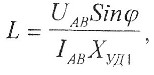
where L - distance to a damage place, km; Uàâ - the vector module phase-to-phase voltage of phases A and B, Â; Iàâ –phases A and  currents vectors difference model( Iaâ = | Ia - Iâ | ); ? - a corner between vectors Iaâ, Uaâ; Ơóä1 - specific jet direct sequence resistance, Ohm/km;
2. At diphasic SC, including diphasic SC on earth
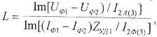
Where Ua1,Uô2,Iô1,Iô2 - first and second damaged phases voltage and current vectors; I2ô(3) - intact (third) phase return sequence current vector turned on 90 °, A; Zóä1 = Róä +jƠóä - specific direct sequence full resistance, Ohm/km.
3. At single-phase SC
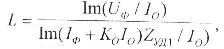
Where U1, Iô - damaged phase voltage and a current vectors; Io - zero sequence current vector, A, Êî - complex factor of indemnification, îïđåöåëÿǻûé under the formula

Where Zóäî - line zero sequence complex specific resistance.
For two-chain AL or two AL, having mutual induction on all line, distance calculation to places single-phase SC is defined on expression
 Where Km - zero sequence intact AL current indemnification factor , defined under the formula Ḱ = Ơóä́/Ơóä1.
For AL with branched substation where the power transformer with the earthed neutral is established, the distance to a place single-phase SC behind branch is defined on expression
 Where L1- AL part from an indicator installation site to branch;
 Ñơ -factor of influence of branch (Ơị̂â - jet resistance zero sequence of branch.
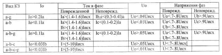
The parities use resulted in tab. 1 is possible.
Damage to any point of electric system is defined on the basis of criterion performance:
Fi=(IàÈÇ̀–IàPAC)2+(IbÈÇ̀–IbPAC)2+(IcÈÇ̀–IcPAC)2→min,
where i - an network place index in which short circuit currents calculation is carried out, i=1, n (ï - tyres quantity; controllable network connecting objects); Fi - value of criterion; IàÈÇ̀, IbÈÇ̀, IcÈÇ̀ - the short circuit currents measured values in phases and, b, from the disconnected switch;IaPAC, IbPAC, IcPAC - values of currents of short circuit in phases and, b, with according to calculation.
Short circuit currents calculation is carried out by the algebraic equations system decision which approximately describe the established condition of phase currents during short circuit. The equations include initial mode resistance which can be calculated on voltage and currents; measured directly before damage and resistance at damage which is set. First of all it is necessary to consider that object which is established as a first analysis stage result. On phase voltages, resistance settlement currents of each model in settlement points are calculated. Only the model which describes type of that damage which has actually occurred, will correspond to most close measured currents. Hence, the damage type can be identified on the minimum criterion value. As the equations for modeling established modes for damages various types at some factors influence modeling is not considered are used: generator transitive currents, elements magnetic systems saturation influence. However, the exact model is not required, while the model describing actual damage type, provides its identification possibility, at models set use.
In a local network short circuit currents calculation on the basis of the model adapted for a current situation [l0] at database use is carried out.
In the block 4 selection of the information concerning object with damage is carried out.
If object with damage is the transmission line that is checked in the block 5 damage place definition on a line is carried out. At expert system use the optimising problem [12] dares:
F=(IàÈÇ̀–IàPAC(k))2+(IbÈÇ̀–IbPAC(k))2+(IcÈÇ̀–IcPAC(k))2→min,
Where K - required point SC which in the search course moves on a line, including and branches.
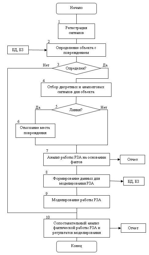
Fig. 2 - The expert system work block scheme
At use registrar of the report formation on a simple logic dependences basis connecting the discrete information is carried out, allowing to make the conclusions. Dispatching messages look like: in «time» Is underlined was disconnected from «RP Name » TL «the line name» with loading «to specify how many ̀Ẩ» with unsuccessful « autoreclosing kind»; the distance to a damage place "is underlined", kind SC "is underlined", «a switch operating time...» etc. More difficult variant is connected with the discrete signals analysis on the basis of knowledge base rules. Type rules: if "condition" that "conclusion" describe a possible situation in object behaviour. So, for transmission lines voltage 110-330 ê with the basic and reserve RP and with autoreclosing formulates 14 main situations. These situations are specified and supplemented depending on the substations scheme. Accordingly, 14 rules are developed, allowing to make the conclusion about SC kind, protection start, protection disconnected SC, autoreclosing work, protection refusal, switch refusal, RP false work, spontaneous switch switching-off. Rules and for other electric network elements are made.
On the basis of the set analysis about the switches changing the position, subsets upon switch switching-off during the controllable time period; to the fact of switch inclusion during the controllable period; to the fact remained disconnected the switch in the controllable period end; to the fact remained included the switch in the controllable period end; sets about various relay operation and comparisons to knowledge base rules the expert system accepts the conclusion. In the block 8 initial data preparation for modeling (a network configuration, initial mode parametres, dithering formation, relay protection construction work logic model) is carried out, and in the block 9 damage modeling is carried out. At blocks work the predicate is used: RZ (ơ, y, z), where ơ - a code identifying type and a protection place, y - a code identifying switches which influences given RP; z - the variable identifying a protective zone given RP. Further the comparative actual work analysis is made sewn up and with the results received at modeling. On the basis of the analysis the report is formed.
Table 1
Parities for SC kind definition (factors will be specified for a concrete network)
LITERATURE:
1. Øàëụ̂ Ă.̀., Àéçåíôåëüä À.È., ̀àëûé À.Ñ. Îïđåäåëåíèå ́åṇ̃ ïîâđåæäåíèé ëèíèé ưëåệđîïåđåäà÷è ïî ïàđà́ạ̊đà́ àâàđèéíîăî đåæè́à. / Ïîä đåä. Ă.̀.Øàëụ̂à. - ̀.: Ưíåđăîạ̀î́èçäạ̀, 1983.
2. Àéçåíôåëüä À.È., Øàëụ̂ Ă.̀. Îïđåäåëåíèå ́åṇ̃ êîđị̂êîăî çà́ûêàíèÿ íà ëèíèÿơ ñ ị̂âạ̊ALåíèÿ́è. ̀.: Ưíåđăîạ̀î́èçäạ̀, 1988. - 160 ñ.
3. Kåzunîvic ̀., Frîmån Ñ. W. Àn Åxđårt Syståm fîr Trànsmissiîn Substàtiîn Åvånt Ànàlysis. - IÅÅÅ Trànsàctiîn în Đîwer Dålivåry, Vîl. 8, Nî. 4, Îctîbår 1993.
4. Kåzunîvic ̀., Rikàlî I. Dåtåct àïä Clàssify Fàults Using Nåuràl Nåts. - IÅÅÅ Cîmđutår Àđđlicàtiîns in Đîwår, Îctîbår 1996.
5. Dàlståin Th., Kulickå Â. Nåuràl Nåtwîrk Àđđrîàch tî Fàult Clàssificàtiîn fîr High Sđååd Đrîtåctivå Rålàying. - IÅÅÅ Trànsàctiîns în Đîwår Dålivåry, Vî1. 10, Nî. 2, Àđri1 1995.
6. Dàlståin Th. åt à1. Multi-Nåuràl Nåtwîrk Bàsåd Fàult Àråà Åstimàtiîn fîr High Sđååd Đrîtåctivå Rålàying. - IÅÅÅ Trànsàctiîïs în Đîwår Dålivåry, Vî1. 11. Nî. 2, Àđril 1996.
7. Äæåé́ñ Ơèëêî. Íîâàÿ ̣åơíèêà èñêóñṇ̃âåííîăî èị́åëëåệà äëÿ đàííåé äèàăíîṇ̃èêè äåôåệîâ àïïàđạ̀óđû. ̀èđîâàÿ ưëåệđîưíåđăạ̊èêà ¹1-2, 1999. - ñ. 31-34.
8. Áọ́êåâè÷ Î.Ô., ÏàALîâñüêèé Â.Â. Ïiäâèùåííÿ åôåệèâíîṇ̃i đîçâ'ÿçàííÿ çàäà÷ îïåđạ̀èâíîăî óïđàALiííÿ åëåệđè÷íè́è ́åđåæà́è çà äîïî́îăî₫ åêñïåđ̣íèơ ñèṇ̃ǻ//̉åîđiÿ ̣à ́îäåëi ïđèṇ̃đî¿â âè́iđ₫âàëüíî¿ i ïåđạ̊âîđ₫âàëüíî¿ ̣åơíiêè: Çá. íàóÿê. ïđ.-Ê.: Ií-̣ åëåệđîäèíà́iêè ÀÍ Óêđà¿íè, 1993.-Ñ. 45-51,
9. Êèđèëåíêî À.Â.,Áọ́êåâè÷ À.Ô.,ÏàALîâñêèé Â.Â. Ưêñïåđ̣íûå ïđîöåäóđû äèàăíîṇ̃èđîâàíèÿ ïđè îïåđạ̀èâíî́ óïđàALåíèè ưëåệđè÷åñêè́è ñạ̊ÿ́è â àâàđèéíûơ ñẹ̀óàöèÿơ//̉åơí.ưëåệđîäèíà́èêà.1995,-¹1.-ñ.66-73.
10. Çàáîëị̂íûé È.Ï., ÏàAL₫êîâ Â.À. Àậî́ạ̀èçèđîâàííàÿ ñèṇ̃ǻà îïåđạ̀èâíîăî óïđàALåíèÿ ëîêàëüíû́è îáúåệà́è ưëåệđè÷åñêèơ ñèṇ̃ǻ. Çáiđíèê íàóêîâèơ ïđàöü Äîíåöüêîăî äåđæàâíîăî ̣åơíi÷íîăî óíiâåđñẹ̀ạ̊ó. Ñåđiÿ: Åëåệđị̂åơíiêà i åíåđăạ̊èêà 21: Äîíåöüê: ÄîíẲÓ, - 2000. - Ñ. 25-28.
11. Çàáîëị̂íûé È.Ï. Đàçâẹ̀èå àậî́ạ̀èçèđîâàííûơ ñèṇ̃ǻ óïđàALåíèÿ ëîêàëüíû́è îáúåệà́è ưëåệđîưíåđăạ̊è÷åñêèơ ñèṇ̃ǻ//Çáiđíèê ̣åç äîïîâiäåé II-¿ ́iæíàđîäíî¿ íàóêîâî-̣åơíi÷íî¿ êîíôåđåíöi¿ "Êåđóâàííÿ đåæè́à́è đîáị̂è îá'åệiâ åëåệđè÷íèơ ñèṇ̃ǻ-2002". - Äîíåöüê, ÄîíÍ̉Ó, 2002. - ñ. 37.
12. Çàáîëị̂íûé È.Ï., Ëàđèí À.̀., Èçåăîâà Í.Í. Đàçâẹ̀èå ́ạ̊îäà ị̂ûñêàíèÿ ́åṇ̃ ïîâđåæäåíèÿ íà AL ïọ́ǻ ưêñïđåññ-àíàëèçà đåæè́à ÊÇ ƯƯÑ//̉åçèñû äîêëàäà. Âñåñî₫çíîăî ñǻèíàđà-ñîâåùàíèÿ "Âîïđîñû ñîçäàííÿ ÀÑÄÓ íîâîăî ïîêîëåíèÿ". Áàêó, 1990.