
Plis Pavlo
Electrotechnical faculty
Speciality: Electromechanics systems of automation and electrical drive
Theme of master's work:
Development of laws control of productivity of mecanisms of aerohydrodynamic group
Scientific adviser: Borissenko Vl.Ph.
Traditional regulatory filing pumping station (PS) - choking pressure dampers, changing the number of working units at the same time - is energetically disadvantageous, because up to 30% of energy wasted is spent on energy loss in throttling device of excess pressure in the network. Most electric motors work in the PS unregulated regime, and thus low efficiency. In regard to the deficiencies of design and operation of electric load factor of many machines does not exceed 50%, which demonstrates the need to reduce the installed engine power. Work is contained in unladen mode leads to large losses. In such circumstances, optimization of the PS, as on the technological requirements, and in conditions of maintaining high efficiency is possible only in regulating the speed of rotation of the pump impeller. The use of regulated electric power allows a smooth change operating parameters of the PS without unproductive cost of electricity and with ample opportunities to improve the accuracy and efficiency of technological process. Allows you to increase the durability of pipelines and equipment by reducing the static and dynamic loads from excessive pressure, reduce the size of the pumping stations due to the increase and decrease the number of pump units. Despite the importance of pumping units, they receive less attention in terms of their improvement, to reduce energy costs, etc. At this time, the PS is one of the most energy consumers in the entire economic complex.
Overview of topic
As an example, consider a pumping station with three pumps (Figure 1). From the supply line 1, in which the pressure varies in the range of 1 to 2.5 atm, pumps H1, H2, H3 pump water discharge mains 2. Under the terms of the technological process of the company in the pressure manifold pressure station to be maintained at 8 atm. The first pump provides the filing range 30 м3/ч≤Q≤90 м3/ч (0,3QH≤Q≤0,9QH), with performance management is carried out by throttling (valves) in the pressure line, which leads to significant losses energy pump supply in the range [1].
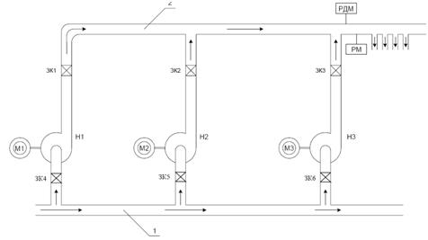
With significant increases in water consumption (more than 0,9QH) includes a second pumping unit and the operator through the valves ZK1-ZK3 manual establishes a value of pressure in the load line and aligns parallel to the load of pumping units H1 and H2. Such a «manual automatics» takes effect every time the regular increase and decrease pressure. Pump H3 - a reserve, he is included in the event of failure of an H1 or H2. On the delivery line are: РДМ - relay pressure main, intended for automation of installation, РM - water meter controlling the flow of pumped water. A distinctive feature of this group of mechanisms are facilitated conditions of their launch. These mechanisms both in normal conditions and after an emergency disconnect start, usually in the blank. This starting point does not exceed 30-35% of the nominal moment. The load on the shaft driving the pump motor can be represented as:
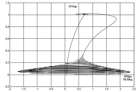
Мст – time starting mechanism; Мср – estimated time of resistance ω=ωH; Мс0 – usually does not exceed (0,05…0,1Мср), where Мср defined as:
For installations with the « ventilatory» load moment resistance smoothly increases with the speed that is consistent with a beneficial form of the mechanical characteristics of asynchronous motor.
In some cases, the start of pumping units with « viscous» body size of the working time of starting can be ten times higher than the values specified above. To implement a successful start-up under such conditions may include rotating engine «back» low frequency voltage to change the consistency of gas. After these preparatory operations, the system is usually run without problems [2].
Existing methods of management of the work of PS
To be a specified mode of operation of the PS in changing the conditions required to regulate operation of pumping installations. This task can be divided into two areas: the regulation of hydraulic pumps operation and regulation of the energy efficiency of the equipment the PS. Regulation of capacity is possible due to manual changes in cross-section of the pipeline in the form of a mechanical device, valves, diaphragms, etc., as well as changes in speed impeller pump installation which is in electric power systems with frequency converters. Covering and opening the shutter, change the steepness of the characteristics of Q-H pipeline (Fig. 3), which depends on its hydraulic resistance.
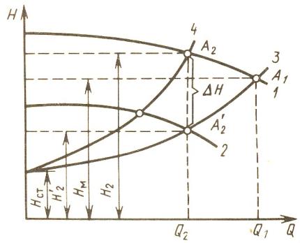
Covering slide, increasing the steepness of the characteristics, the working point of the pump A1 moves to A2. with the filing of Q2 is reduced to meaning head, developed the pump increases to the value H2, and the pressure on the pipeline for the gate is lowered to values of H2' at the expense of loss in ΔН closures. Increasing the degree of opening of the shutter, reduce steepness of the characteristics of the pipeline. Consequently, the feed increases, the pressure developed by the pump decreases, and the pressure in the pipeline for the gate increases. This method of regulation maloekonomichen as well as to overcome the additional hydraulic resistance to shutter requires additional energy. When you change the speed of the pump changes the characteristics of Q-H pump. Reduce the frequency of rotation, moving testimonial down parallel to itself. In doing so, the working point, moving to the characteristic line, took a position A2', hence the supply decreases, as well as the pressure in the network and the head developed by the pump. In modern pumping stations (PS) are two main types of management performance - and the cascading frequency. Cascade regulation is to enable or disable parallel set of pumps. The accuracy and efficiency of regulation while the amount of installed pump units. Frequency regulation can adjust the performance of pump stations by changing the speed of pumps with a converter frequency (CF). The best, in terms of techno-economic indicators, a way to control when the inability to provide a desired pump performance of PS in the work include the following. The first motor is connected directly to the supply network, and enters into the work - is displayed on the operating frequency with the help of CF. Productivity of the second pump will be determined by the expression:
Q1H – nominal output first pump unit; Qс – consumption in the network are currently; ΔQп – losses in the hydraulic network [3]
For uniform wear of the engines are also advised to change their order of connection. A simplified scheme of this method is shown in Figure 4. The control flow and pressure is carried out in specific locations have the network. This information is transmitted to the programmable logic controller (PLC),
where a comparison of current values of monitored parameters from a given, and make managing the impact of the regulatory system. PLC handles coming to it by the signals from the flow sensor and pressure effect on CF, which alters the speed of the drive motor pump unit, and manages the connectivity required number of engines to ensure consumer needs. Special CF can replace PLC as the logic is already inside them. It should be noted that modern CF able to regulate the filing of a schedule, and for a given flow rate. Application of the controlled drive pump provides the PS in the zone of optimal efficiency. A cascade frequency regulation performance PS optimizes the efficiency of the pump units in a time of productivity, reduces by 50-70% energy consumption and contributes to the durability and longevity of a water supply system components [4].
Conclusion
There are currently developed ideological, organizational, and circuit aspects of the application of frequency-controlled drives. Developed and tested various techniques to determine the economic impact of their introduction, to calculate the required power converter. But the effectiveness of the use of frequency regulation is the «individual», and requires in each case, the study object, that is, determining the characteristics of networks and pumping units, the calculation taking into account the specificities and characteristics of the facility and its equipment. And yet, there remain a number of pressing problems that are associated primarily with the stabilization of pressure to have the points, eliminating hydraulic shock in determining productivity sharp fluctuations in inlet pressure and flow at the exit station [5]. The situation is exacerbated by the network and its shut-off devices, and also because of the lack of accurate information about the processes occurring in different parts of the network. For the analysis of unsteady transition in complex hydraulic networks, followed by exposure to the executive body is supposed to use neural networks and the odd logic (fazzy-logic). The first is a computational structure, adaptable and trained by analyzing positive and negative impacts. This mathematical model, as well as parallel computing devices of a system of connected and interacting simple processors (artificial neurons). Regarding the odd logic, it gives the right to obtain sustainable solution in terms of error information and fuzziness of production constraints in the form of membership functions. Odd logic enables the formalization of imprecise knowledge about the system, making the model the details of the incompleteness of information, significantly reduces the possibility of inconsistent decisions in the calculation and optimization.
Literature
- Электромеханические системы автоматизации стационарных установок/ Под общ. редакцией проф. Борисенко В.Ф., Донецк: ДонНТУ, НПФ МИДИЭЛ, 2005. – 281 с.
- Борисенко В.Ф., Григорьев С.В., Моргунов В.М. и др. Вопросы повышения производительности нагнетательной станции средствами электропривода. Машиностроение и техносфера ХХІ века// сб. трудов МНТК в г.Севастополе 13-18 сентября 2004 г., Донецк: ДонНТУ, т.1, 73-75 с.
- Лезнов Б.С.Экономия электроэнергии в насосных установках. – М.: Энергоатомиздат, 1991. – 144 с.
- Борисенко В.Ф., Поляков В.А., Плис П.С. Анализ каскадно-частотного регулирования производительности насосных станций// Сборник статей кафедры «Общая электротехника» ДонНТУ, 2009.
- Коренькова Т.В. Насоси. Особливості включення. Характеристики насосів і режимів енергоспоживання при перемінній швидкості обертання: Навч.посібник. – Кременчук: КДПУ, 2002. – 56 с.
- Ключев В.И., Терехов В.М. Электропривод и автоматизация общепромышленных механизмов: Учебник для вузов. – М.: Энергия, 1980. – 360 с., ил.
- Башарин А.В., Новиков В.А., Соколовский Г.Г. Управление электроприводами: Учебное пособие для вузов. – Л.: Энергоиздат. Ленинг. отд-ние, 1982. – 392 с., ил.
- Шлипченко З.С. Насосы, компрессоры и вентиляторы. – К., «Техніка», 1976, 368 с.
- Под ред. Новикова В.А., Чернмгова Л.М. Инжиниринг электроприводов и систем автоматизации. – М.: Издательский центр «Академия», 2006. – 352 с.
- Виноградов А.А., Сибирцев А.И., Колодин И.В. Автоматизация насосной установки с применением частотно-регулируемого электропривода//Силовая электроника №2, 2006. [Электронный ресурс], – http://masters.donntu.ru/2008/eltf/sukiasyan/library/letter1.htm