-
 Abstract
- Introduction
- The purposes and problems
- Mathematical model
- Establishment of optimum parametres of a safety barrier
- Conclusion
- Literature
 Introduction
Coal in Ukraine is the main source of energy, so the work of the coal industry depends the state of the economy. Mine transport is one of the most important links in the coal industry. Very important are the security aspects in the conduct of work on big depths. All this requires increasing the safety operation of the means of delivery of cargo to support the lower horizons. The cable is a haulage vehicle coal Ukraine mines, which should be highly reliable and safe operation. One option for these requirements is to improve the safety rope haulage on means of improving the system of emergency braking cars [1,2,3].
The present work is devoted this question.
 The purposes and problems
The work purpose is safety increase for the account of a well-founded choice of parametres of means of catching of cargo trolleys in inclined developments of mines.
 Mathematical model
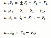
And the basis of a principle of Dalambera the differential equations of a movement of the train register in a kind [7]:
(1)

where
Fт – force of draught (+) or braking (-), enclosed to weight of the first trolley in structure т, kN;
mi – weight of a car, kg;
xi – co-ordinate of the centre of weights of a i car;
Si – effort in a i car;
Fi – force of resistance of a i car;
n – quantity of cars.
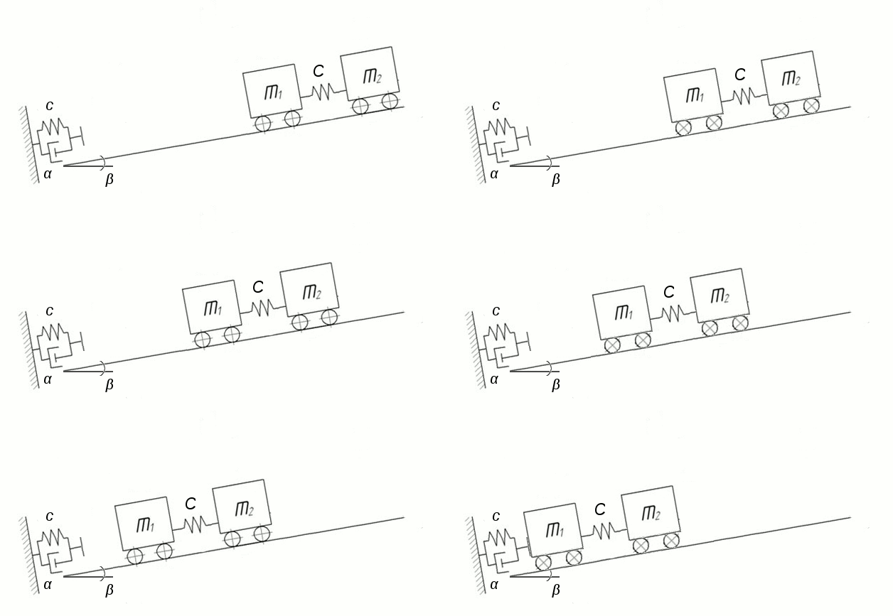
At research the structure of trolleys is considered as system of firm bodies mi connected by elastic communications, and a barrier – as the shock-absorber with snubber, strengthened on a rigid support (the viscoelastic buffer) (figure 1).

Figure 1 – The settlement scheme
(Animation consists of 7 shots, 100 KB with a delay in 0,5 with between shots; the delay before repeated reproduction makes 2с; the quantity of cycles of reproduction is not limited)Movement of cars at braking is described by the equation (1). Entry conditions in case of structure braking: xi = 0; x'i = v; i = 0,1,2...n (when t = 0). Then dynamic loading:
(2)

where
c — ruggedness of a safety barrier, N/m;
α – factor of viscous resistance, N⋅c/m.
Force of resistance to movement of cars as a part of a train in case of them movements under a bias is defined by following expression [8]:
(3)

Reaction of elastic communication between the first and second cars of structure looks as follows [9]:
(4)

where
c — ruggedness communications, MN/m,
ε1 – lengthening of elastic communication centre to centre weights of the first and second cars.
Let's write down the equation for communication of the first and second cars:
(5)

Dynamically loadings in buffers and frames cars at structure braking it is defined from dependence:
(6)

The received expression allows to define the maximum values of shock loadings for any car of structure at braking of a train depending on ruggedness of communication and distance between buffers of cars.
Forces of inertia:(7)

where
Mпр — The resulted weight of moving parts, kg:
(8)

where
k0 — the factor which considers inertia of rotating parts of a trolley.
Proceeding from the aforesaid it is made mathematical model. Movement of the broken structure can be divided into two stages conditionally.
The first stage weeps from the moment of breakage and to the moment of interaction with a safety barrier. Then the equation of movement of the first trolley will become:
(9)

The second – since the moment of contact piece of a car and a trapping barrier and to a full stop. In this case there are longitudinal dynamic loadings caused by braking of structure of cars. For their account in mathematical model we enter influence communications on (6). Then the equation of movement of the first car on (1):
(10)

From (6) and (10) we receive definitive mathematical model:
(11)

where
b — the relation of weight of a trolley to weight of structure:
(12)

F1 — force of braking by a safety barrier:
(13)

 Establishment of optimum parametres of a safety barrier
The established interrelation between parametres has given the chance to receive optimum values of indicators of a safety barrier. Optimisation was spent by means of the orthogonal plan of the second order with four factors (speed, quantity of trolleys, ruggedness and viscosity of a safety barrier) which varied at five levels (table 1) [10].
Table 1 — Levels of a variation of factors
Levels and intervals of a variation of factors Factors Variation levels Names Dimension Designation Code Variation intervals Natural Node -1,41 -1 0 1 1,41 Natural Ruggedness of a barrier MN/m C X1 10,9 15 25 35 39,1 10 Viscosity of a barrier MN⋅s/m α X2 0,03 0,2 0,6 1 1,16 0,4 Speed of the approach to a barrier m/s v X3 5,59 6 7 8 8,41 1 Quantity of cars piece. N X4 1,18 2 4 6 6,82 2
Optimisation parametre - the maximum loading on a barrier. The equation of regress of the second order which after an exception of non-significant factors has assumed the following air [11,12] has been as a result received:
(14)

Construction of dependences for reception of curves of the response have made, manipulating real values of factors for structure from 3 cars of type ВГ 3,3 at the maximum speed of the approach to a barrier of 7 m/s and a discharge angle of development equal 20°. As a result following schedules have been received.

Figure 2 – Dependence of the maximum loading on a safety barrier from viscosity of a safety barrier α ruggedness c at the approach of structure of trolleys to it about speed v and quantity of trolleys in structure N .
 Conclusion
On the basis of the spent probes the mathematical model describing movements of the train of trolleys at emergency descent under a bias is received. The mathematical model connects major factors influencing behaviour of structure, such as resistance to movement, a development discharge angle, initial speed before breakage, ruggedness and viscosity of a barrier, and influence communications.
On the basis of the spent probes разработанна a design of a safety (trapping) barrier which allows to raise considerably safety in inclined developments of mines – for the account of sectioning, cheapness of a design and simplicity of operation. Literature
- Бурлака Г. О. Угольная промышленность // ТЭК . – 2006 . – № 7 . – С. 66–69.
- Транспорт на горных предприятиях. Под общей редакцией проф. Кузнецова Б.А., М.: “Недра” 1976, 552с. Авт.: Кузнецов Б.А., РенгевичА.А., Штокман В.Г. и др.
- Гриф Б.В., Горчаков С.П. Охрана труда в угольной промышленности.– М.: Недра, 1988.
- Будишевский В.А., Деревянский В.Ю. Повышение безопасности канатной откатки // Уголь Украины, 1998. - №3. – с.25-26
- Дебелый В.Л., Дебелый Л.Л. О модернизации электровозов АМ-8Д и 2АМ-8Д в ходе капитального ремонта // Уголь Украины, 2007. - №4. – с.23-24
- Способы и средства безопасной эксплуатации электромеханического оборудования в шахтах // Сб. научных трудов. Макеевка: МакНИИ, 1982.-С.53-57.
- Введение в теорию динамики горнотранспортных машин. Новиков Е.Е., Смирнов В.К., К., «Наукова думка», 1987. –173с.
- Динамика и прочность шахтных транспортных сосудов/ Е.Е. Новиков, Е.Ф. Земляной, В.В, Говоруха и др. – Киев: Науккова думка, 1983. – 152с
- Шахтарь П.С. Рудничные локомативы. М., Недра, 1982. – 296 с.
- Планирование и анализ экспериментов при решении задач трения и износа. М.: Наука 80. — 228 с.
- Тихомиров В.Б. Планирование и анализ эксперимента. М.: Недра 74.—304 с.
- Адлер Ю.П. Планирование эксперимента при поиске оптимальных условий. М.: Наука 71
- Методы планирования эксперимента [Электронный источник] http://elib.ispu.ru/library/lessons/Kazakov/
- Нарышкин В.Н., Коросташевский Р.В. Подшипники качения. М.: Наука 1984
