 |
Krivolapov PavelElectrotechnical facultySpeciality: Electromechanic systems of automation and electric driveTheme of master's work:Research of two-band regulation of speed at the modern systems of electric driveScientific adviser: Tolochko Olga |
Introduction
Actuality of theme.The system of two-band regulation of speed can be examined in the drives of direct current, at the drives of alternating current with asynchronous motors with the vector and scalar regulation, also two-band regulation mode can be realized in brushless DC motors.
The aim of this work is: study and description of the system of the two-band regulation of speed, research of dynamic properties of different variants of adjusting charts.
Task: to execute the comparative analysis of the systems of the two-band regulation of speed the method of mathematical design, to develop recommendations on their application, construction of observer for the selection of signal speed in the two-band system.
The review of researches on the topic in Donetsk National Technical University: this questions examined Tolochko O.I., Kocegyb P.H. [1-4].
This theme is disseminate, therefore it was studied by the great number of authors as in Ukraine and in other countrys. It is possible to select among them [5-11].
Main results
Scalar regulation. Combination of two modes of frequency regulation U1/f1 and U1=const.enables to get the two-band regulation of speed in asynchronous motors. The special feature is only in that fact that the regulation of speed at the frequency control is carried out by the change of frequency in both areas, and the mode of regulation by the flux is determined by the law of voltage regulation.
Vector regulation. If two-band regulation of speed is required, the function generator will be provided in the system. An input signal on it will be determined by the value of speed.
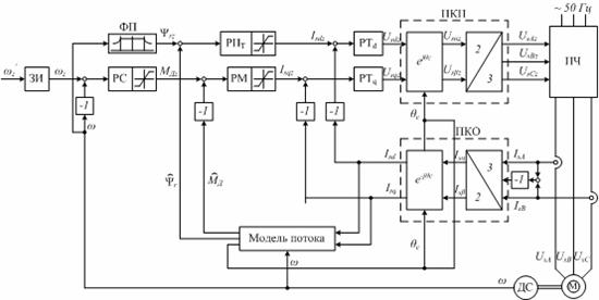 |
Figure 1 – System with vector regulation |
Brushless DC motors. At the two-band speed regulation, in a rage from zero to nominal speed the equality of constituent of current of stator to the zero is supported on the axis d and simultaneously frequency and voltage of frequency converter change, and in overhead part of range, when voltage attained the nominal it’s value and further increase is impermissible, only frequency is multiplied, and current on the axis d is not supported equal to the zero.
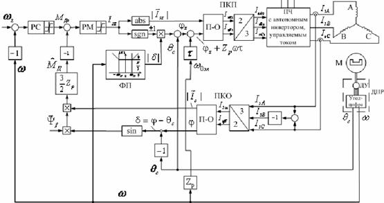 |
Figure 2 – System with brushless DC motor |
Drive of direct current (DC). Principle of regulation of speed, based on property of DC to change speed under the action of change of field flux, found application. This is because demands of rev-up treatment of wares and increases of the productivity. These systems got the name of the systems of the two-band regulation of speed.
The system of two-band regulation of the DC motor will be investigated on the base of direct-current drives Mentor II, field controller FXM5 and sensor of speed.
Depending on requirements to descriptions of electromechanic the various charts of regulation can be utilized:
1) control of motor ar mature chain and field circuit which work independent from each other (separate control)
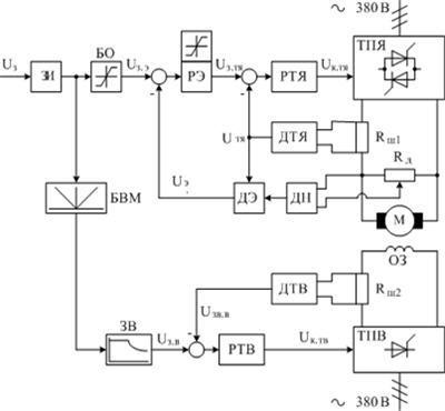 |
Figure 3 - Separate control (functional design) |
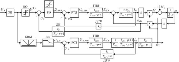 |
Figure 4 - Separate control (flow chart) |
2) control the field circuit according to some parameters – EMF or voltage of electric motor (dependent control);
3) system which is middle between the systems with a dependent and separate control (adjusting subsystem to basic speed, as well as in the systems with a dependent control, and subsystem of adjusting of field circuit, as in the systems with a separate control);
Let’s consider separate regulation in detail, because this theme will be investigated in the nearest time (fig.3 and fig.4).
Systems of two- band regulation with the separate agency of stream field of motor, foremost, are the systems of the indirect adjusting of speed. That is to say instead of contour of adjusting speed either EMF control loop (ECL) with a EMF regulator (ER) or voltage control loop (VCL) with a voltage regulator (VR) can be used.
Passage to the feed-back on EMF or voltage in a basic contour eliminates the use of principle of dependent control of flux in an common variant, as in the area higher than basic speed the signal of feed-back will never be able to attain the signal of assignment of RAMP. That is why a necessity for the separation of the modes of control of voltage of converter and flux of the motor.
In this figure DA is a dividing amplifier, intended for the division of adjusting areas. His initial voltage is limited on the level proper to nominal EMF (voltage) of motor. The setting of DA is limitation of signal of task that acts with RAMP, as EMF and voltage, instead of speed, remain constant at the change of flux.
The passage of the system control to the second area is carried out by master of field circuit – MFC at the proper signal of RAMP. With, at the initial signal of RAMP to the proper signal of task speed more than nominal MFC reduces the signal of task on excitation.
Only ECL at Φ=const works with ω>0 and ECL at Ed=const works with ω≤0. For this figure main question is to define analytical expression of description of MEC, that to define how initial voltage of MFC should change depending on the signal of RAMP. The type of description of MFC depends on which from one parameters at an acceleration should be supported as constant Mj or Ij. Let’s show out descriptions of MFC for two variants. It is not important which the main contour will be. We will consider that a basic contour will be closed on EMF.
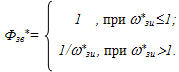
a) MFC at Mj=const
During the work in the first area an initial signal of MFC must be constant and answer the nominal field flux. All this can be written down as equation:
 |
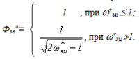
b) MEC at Ij=const
Initial description of MFC in the first area is known as constant and equals tothe nominal field flux. All of the conclusions, resulted above, are written in for ω>ω0, that for the second area. In the general view (for both areas of adjusting) of equalization of initial description of MFC at Ij=const it is possible to write down in such way:
 |
At simulating such graphs were obtained (fig.5):
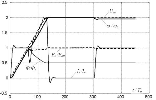 |
Figure 5 - Graphs at separate control |
Master's work is not completed yet. Final completion: January, 2010. The complete text of work and materials on the topic can be got for an author or his adviser after the indicated date.
1. Толочко О.І. Системи непрямого регулювання швидкості зі спостерігачами стану /Толочко О.І., Песковатська О.В., Кудокоцев С.М.; Наукові праці ДонНТУ. Серiя “Електротехніка i енергетика”. – Донецьк: ДонНТУ. – 2003. – №67. – С. 168-173.
2. Толочко О.И. Сравнительный анализ систем двухзонного регулирования скорости /О.И. Толочко, П.А. Максаев; Проблемы создания новых машин и технологий. Научные труды КГПИ. – Кременчуг. – 1999. – №2 – С. 32-35.
3. Толочко О.И. Системы двухзонного регулирования скорости с наблюдателями состояния /Толочко О.И., Максаев П.А., Мариничев В.Ю.; Проблемы создания новых машин и технологий. Научные труды КГПИ. – Кременчуг: КГПИ. – 2000. – №1(8). – С. 53-56.
4. Толочко О.И. Системы двухзонного регулирования скорости /О.И. Толочко, П.А. Максаев/ Проблемы создания новых машин и технологий. Научные труды КГПИ. – Кременчуг: КГПИ. – 1998. – С. 28-31.
5. Виноградов А.Б. Векторное управление электроприводами переменного тока / ГОУВПО «Ивановский государственный энергетический университет имени В.И. Ленина». Иваново, 2008. 298с.
6. Усольцев А.А. Частотное управление асинхронными двигателями/Учебное пособие. СПб: СПбГУ ИТМО, 2006, – 94с.
7. Перельмутер В.М. Системы управления тиристорными электроприводами постоянного тока/В.М. Перельмутер, В.А Сидоренко - М.: Энергоиздат, 1988.
8. Чиликин М.Г. Общий курс электропривода/М.Г. Чиликин, А.С. Сандлер - М.: Энергоиз-дат, 1981 г.
9. Казачковський М.М. Комплектні електроприводи: Навч.посібник / Дніпропетровськ: Національний гірничий університет, 2003. - 226с.
10. Зимин Е.М. Электропривод постоянного тока с вентильными преобразователями - М: Энергоиздат, 1981, – 192с.
11. Walter N. Alerich Electricity 4: Ac/Dc Motors, Controls, and Maintenance. еdition:7, Cengage Learning, 2001, pp: 360
12. Dale R. Patrick Rotating electrical machines and power systems. edition:2, The Fairmont Press, Inc., 1997 pp: 399
13. Чалый В.В. Синтез Систем управления электромеханическими обьектами с применением интеллектуальных модулей на основе оборудования фирмы Control Technique [Электронный ресурс] / Портал магистров ДонНТУ – http://masters.donntu.ru/2008/eltf/chalyy/index.htm
14. Модель двигателя постоянного тока (регулирование скорости во второй зоне) [Электронный ресурс] / Официальный сайт компании MathWorks http://www.mathworks.com/matlabcentral/fileexchange/12137-pid-and-state-feedback-control-of-dc-motors