ABSTRACTof the qualification master’s work DonNTU
Aleksandr Krivtsov Improved functional parameters of automatic electric drive of belt conveyor the colliery on the basis of application of thyristor regulator rotor current
At present time controlled electric drive of trunk belt conveyor is equipped with wound-rotor
induction motor (IM) and explosion-proof liquid rheostat (EPLR). Such electromechanical systems are characterized by composite construction
, large number of movable parts, accessory electric drives, considerable dimensions, high-mortality and low reliability.
Therefore an actuality of such electric drive systems improvement is based on application of
power thyristor regulators.
The purpose is to increase of effectiveness and service life of electric drive of trunk belt
conveyor based on application of rotor current thyristor regulator (RCTR).
To accomplish this purpose it is necessary to resolve the following problems:
1. To analyze the belt conveyor as an automation object
2. To perform an analysis of IM settings control modes and devices
3. To prove the research guidelines
4. To carry out the theoretical study applying mathematical or computer simulation of processes
in electric drive considering efficient improvement
5. To develop functional and structure diagram of improved drive control unit
6. To develop basic automation diagram and describe its operating principle.
Belt conveyors are widely used at coal mining and other mineral resources, in areas where
operating space is utterly limited.
Trunk belt conveyor is used for coal mass transportation horizontally and in inclined direction.
Belt conveyor enables not only transportation of output products from the mine, but also the delivery of necessary tools and materials to
the mine workings location (this is achieved owing to provided by reversing feature).
Overwhelming majority of belt conveyors is equipped by non-adjustable speed electric drives based
on wound-rotor IM. Lack of effective speed control tools narrows functional features of the drive unit, causes excessive wear of its
components. Intensive acceleration of operative parts of mining plant fairly often leads to operating staff injuries. Therefore the urgent
problem is development of controlled electric drive for mining plants.
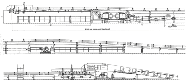 Figure 1. - Overall view of belt conveyor LT800
Rotor current controller is used for providing step or slide speed control of wound-rotor IM.
It enables to get the series of artificial mechanical characteristics and to control speed within wide range.
A large number of devices are used for rotor current control. One of them is rheostat control
circuit of acceleration of driving induction motor (IM), which by-turn can be realized as EPLR. Operation practice has shown quite a number
of disadvantages of using liquid rheostats. They are the following: low reliability due to using of considerable number of movable parts of
power circuit: electric motors of rheostat blades (4), electrolyte (1) pump (7, 8) and air heater (9 -11) for its cooling. [6]
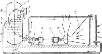 Figure 2 – Explosion-proof liquid rheostat device EPLR
The next variant of rheostat circuit is application of rheostat resistors cut in circuit of IM
rotor. It enables to get the series of artificial mechanical characteristics and to control speed within wide range.
At the same time, there is a possibility of combination of rheostat control principles with rotor
current control based on application of proximity regulator and one stage of rotor resistors. Three-phase thyristor switch can be used as
regulator, consisting of three couples of back-to-back connected thyristors [7] with in-series active resistance, or bridge rectifier,
loaded by active resistance with parallel thyristor switch [8]. In the last case the dependence of phase symmetry of induction motor rotor
current on probable values inequality of rotor resistors in phase is eliminated, and that is more acceptable for ensuring long service life
of IM. [6].
Figure 3 - The principle of work with BP included in the chain of the rotor rheostat resistances
(Animation 1:
volume - 34.4 kb; size - 203х600; number of shots - 8; delay between shots - 1 s; delay between the last and first shots - 3 s; number of
repetition - infinity. Animation 2: volume - 100 kb; size - 684х600; number of shots - 8; delay between shots - 1 s; delay between the last
and first shots - 3 s; number of repetition - infinity.
At present rheostat circuit with rotor current thyristor switch [4] is realized in
factory-assembled electric drive unit UPTF [2] by Estel Plus AS enterprise (Estonia) [8].
Absolute advantage of such drive unit should be considered common active rotor resistor circuit
for all three phases of IM rotor.
IM engine torque control at any of artificial mechanical characteristics is carried out by means
of phase change of rotor current by controlled rectifier (U). An operation specific of this rectifier is conditioned by unstable frequency
of rotor electromotive force. This conditions the actual problem of equalization of firing angle ? for rectifier thyristors within
frequency range from 50 Hz (IM start up) up to 1,5 Hz (IM running at rated speed).
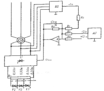 Figure 5 - Power circuits drive the device UPTF and elements of management
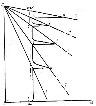 Figure 6 – Starting diagramme of the electric drive:
1,2, …, 5 – static mechanical characteristics;
a-b-c-d - … - m-n-ωc – dynamic characteristic
This problem is resolved by pulse-phase control system circuit where reference voltage U16
defining the firing angle ? of thyristors is specified by-turn inversely to the frequency of electromotive force of Uc rotor (Fig. 7) [3].
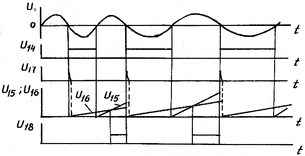 Figure 7 – Voltage diagram of pulse-phase control circuit for АС 1504756
RCTR illustrates thyristor switch diagram at three couples of back-to-back thyristors, connected
to resistance load. Conversion of conveyor drive motor to normal mechanical characteristic is realized by contact short-circuiter КМ1 of
rotor circuit.
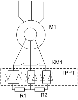 Figure 8 – Adaptation of electric drive circuit with rotor current thyristor regulator (RCTR) to the conditions of
application in mine belt conveyor unit (КМ1 – Contact short-circuiter)
Figure 8 – Adaptation of electric drive circuit with rotor current thyristor regulator (RCTR) to the conditions of
application in mine belt conveyor unit (КМ1 – Contact short-circuiter)
However the following problem occurs during synchronization of pulse-phase control circuit
operation for RCTR. There exist several solutions for this problem. One of them is transformer triggering [5]. Though frequency
instability of these electromotive forces conditions technical contradiction in according to which it’s impossible to use transformer
triggering facilities, as it is usually done at stable voltage frequency (electromotive force) of synchronization. In addition, it is
necessary to match the values of synchronizing voltage with supply voltage of drive control system elements particularly pulse-phase
control circuit.
Acceptable solution for this technical contradiction is performing of synchronization unit based
on application of three-phase voltage divider (Fig.9). As far as resistors of this divider are star-connected, its potential (zero) is
coordinated with the potential of common feed circuit output for electronic devices of drive control system (provided that R1-R3 resistors
are connected by first outputs to the clamps of phase voltage of IM rotor). Resistance ratio of resistors R1-R3 and R4-R6 can be chosen
that phase voltage drops at resistors R4-R6 will be amplitude proportioned to the value of positive supply voltage of electronic devices
of control system. Therefore, using of three-phase resistor voltage divider does not contradict the problem of matching the value of
supply voltage of control system electronic devices with higher values (about 500 V, at stator voltage 660 V) of electromotive force of
IM rotor.
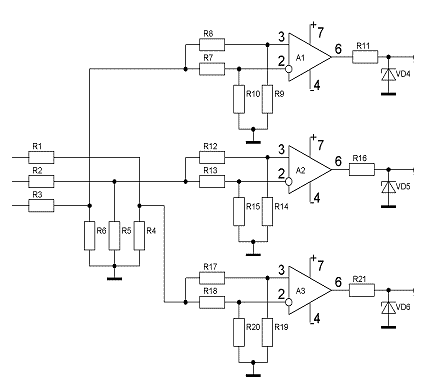 Figure 9 - Diagram node synchronization pulse-phase control system on three-phase voltage divider
Therefore, the proposed technical solution is characterized by simplicity, enables to resolve
the problem of synchronization of three-phase system of high-level electromotive force and variable frequency with pulse-phase control
circuit, does not require transformer or other (e.g. optronique) galvanic isolation technical facilities.
References
1. Стадника М.І. Довідник з автоматизації шахтного конвеєрного транспорту / [Стадник М.І.,
Ільюшенко В.Г., Єгоров С.І. та інщі] за ред. Стадника М.І. – К.: Техніка, 1992.- С. 63-79
2. Борисенко В.Ф. Электротехнические системы транспортных механизмов / [Борисенко В.Ф.,
Чепак А.А., Сидоров В.А., и др.] под ред. Борисенко В.Ф. – Донецк.: НПФ «МИДИЭЛ», 2007. С. 83-89
3. Маренич К.Н. А.С. 1504756 СССР, МКИ3Н02М5/22 Устройство для импульсно-фазового управления
тиристорными регуляторами напряжения / К.Н.Маренич, И.Т.Сидоренко, С.В.Дзюбан, В.Н. Пименов (СССР). - №4341676/07; заявлено 11.12.1987;
опубликовано 30.08.1989. Бюл. №32
4. Кривцов А.А. Севергеоэкотех-2009: труды Х междунар. конф., 18-20. 03. 2009 г., Ч.1.
Кривцов А.А / Ухта: УГТУ, 2009.- С. 78-80.
5. Кривцов А.А. Севергеоэкотех-2010: труды ХI междунар. конф., 18-20. 03. 2009 г., Ч.1.
Кривцов А.А. / Ухта: УГТУ, 2010.- С. 76-87.
6. Малиновский А.К. Автоматизированный электропривод машин и установок шахт и рудников.
Малиновский А.К. / М.: Недра, 1987.- 277с.
7. Маренич К.Н. А.С. 1824835 СССР, МКИ В65С23/00 Способ управления пуском шахтного ленточного
конвейера и устройство для его осуществления. К.Н. Маренич, С.В. Дзюбан, И.Т. Сидоренко и др. (СССР), опубл. 05.02.1990
8. Estel Plus AS Устройства УПТФ (ЭПТФ). Рекламная информация. [Electronic resource]
/ Estel Plus AS/ - Access mode to articlewww.estel.ee
9. АОЗТ "Инстройсервис" Состав аппаратуры САУКЛ [Electronic resource] / АОЗТ "Инстройсервис" /
- Access mode to article instroyservis.com
10. Ляшенко Н. І. Склад АПМ / Н. І. Ляшенко, А. В. Панасенко – інженери
(шахта ім. Бажанова), В. Н. Зеленецкий, інженер (ВАТ "Автоматгормаш")
11. БИКОВСЬКИЙ А. П. Состав АПМ УДК 622.647.25:621.31: / А. П. БИКОВСЬКИЙ, В. Н. ЗЕЛЕНЕЦКИЙ
, інженери, И. З. КИБРИК, канд. техн. наук (Аатоматгормаш), І. Т. СИДОРЕНКО, К. Н. МАРЕНІЧ, кандидати техн. наук (ДонНТУ)/
12. Батицкий В.А., Автоматизация технологических процессов и АСУ ТП в горной промышленности:
Учеб. для техникумов. / Батицкий В.А / – 2-е изд., перераб. и доп. – М.: Недра, 1991. – 303 с.: ил.
13. Малиновский А.К. Автоматизирований электропривод машин и установок шахт и рудников: Учебник
для вузов. / Малиновский А.К. / – М: Недра, 1987. – 202 с.
Note
The final conclusion for MA course qualification research will be defined by the end of 2010.
|