
Faculty: Computer Information Technologies and Automation
Speciality: Automatic Control of Technological Processes
Theme of master's work: Automation of coal preparation process using vibration-pneumatic separator
|
|
|
|
|
|
|||
|
Vadim Loginov Faculty: Computer Information Technologies and Automation Speciality: Automatic Control of Technological Processes Theme of master's work: Automation of coal preparation process using vibration-pneumatic separator |
|||||||
|
|
|
|
WPC. Thought that has become a thingTracing a story of little homemade deviceThe idea, development, assembling – Vadim LoginovOnce I faced a necessity of a device for controlling water pumping. The thing is that I had to turn on the pump and check water level every 20 minutes. After water goes down I had to turn the pump off to prevent its damage. But it is very annoying... Thanks God, I am automation engineer! I decided to make a simple device which would do this check work for me. So... Goal – device for automation of home "dewatering plant" (it sounds too serious...) So, what should I begin with? I think the best is to determine what must do out device (let's name it WPC, device for water pumping control) WPC functions
A structure chart of WPC is shown on fig.1. 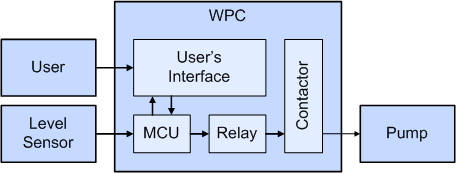 Figure 1. The structure chart There are several functions. But how should the WPC behave to be able to execute them all? WPC operation modes
AlgorithmWell, let's see how WPC will "think" while doing it's job (fig.2) 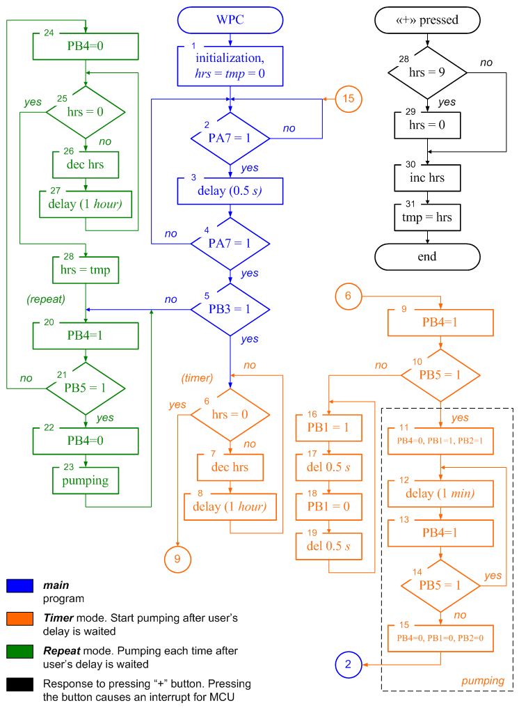 Figure 2. The WPC algorithm CircuitryI've chosen ATtiny26 to be the heart of WPC. 7-seg LCD indicator is used to indicate "hrs" and making "pumping" animation. 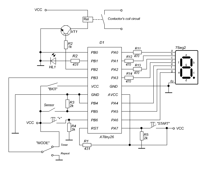 Figure 3. The WPC circuitry And PCB, of course. See fig.4 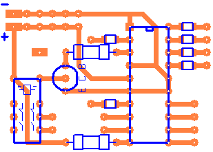 Figure 4. The WPC PCB Practical realizationIn next pictures you will see all steps I accomplished to make a circuit board for WPC 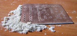 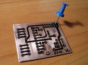 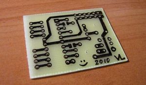 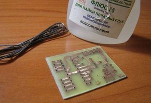 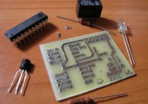 Almost done! Let's see how do out activities correlate with a structure chart mentioned before 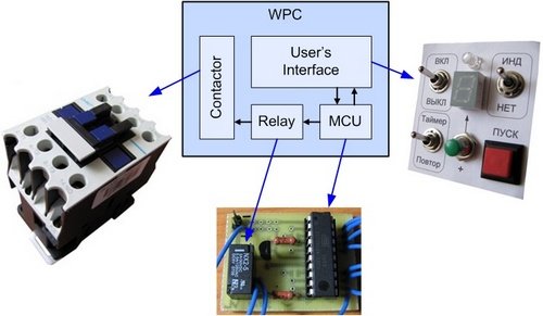 Figure 5. Almost ready for assembling Did I forget something? Oh, of course! Our microcontroller is not "alive". The program! I'll write the program in AVR Studio. You may see the code in the listing. Done! The final result is shown at fig.6 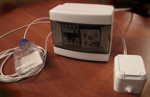 Figure 6. Here is out new device DemonstrationIn order you to look how this stuff works I made a short movie (link here if there is no video below) Well, it's time to say goodbye. Thank you for your interest and patience. All the best! © 2010 Vadim Loginov |