
Introduction
Geometric modeling systems are widely used in all spheres of human activity. Their features, principles and methods depend on tasks, which they decide. There is no universal graphics tool that can simulate any real process or object. Widespread automation of production processes, has led to the appearance of software products aimed at both the individual stages of production so the cycle of production in general.
Often, such systems do not meet all the requirements of the problem and complicate the process of its solution. In this case, the creation of a new system from scratch is a tedious process, the cost of developing and implementing a new tool could significantly exceed the useful effect of its use. Therefore, as a basis for such system is useful to have some code with a set of base classes and operations on them, not dependent on task of application. This can be a set of libraries, and a full framework that allows to design interactively the architecture of future systems.
Within the plan of master work a library of classes and functions is developed, on the basis of which will be designed and implemented a system of geometric modeling, allowing you to create three-dimensional models of objects based on their two-dimensional representations. The work is based on the master work written by Hlepitko Igor entitled "Research instruments of development geometric modeling system". Established as part of this work, a graphical library for working with basic geometric objects: line, circle and ellipse, was expanded by the addition of operations of building 3d-model for projections of the curve of arbitrary form.
Developed system allows online creation and editing of conical surface on the basis of their two-dimensional representations.
Actuality of theme
Development of new graphic design systems requires considerable time and money consumption, so the problem of optimizing the development process of graphics systems is highly relevant.
Communication of complex drawing and three-dimensional representation, is no less urgent problem in computer-aided design.
Design documentation is traditionally performed on an integrated drawing and receive a visual image of a constructed facility, is very useful for solving problems of ergonomics, aesthetics and technical design. Of particular importance to the solution of this problem is in the training process, when the student isn't have enough developed spatial imagination to link the complex drawing object with its three-dimensional representation.[1]
Purpose and tasks
The purpose is creation of basic set of software components, the use of which significantly accelerate the development of geometric modeling systems, complementation and improvement of the already existing class library.
Problems to be solved during the work:
- A study of existing solutions in this area, identifying their strengths and weaknesses
- Development and implementation of the core, that could be applied as a base to create a geometric modeling system
- Implementation of the educational geometric modeling system, to work with a virtual complex drawing and the binding of two-dimensional constructions with three-dimensional model
The novelty of the work
There will be developed an algorithm relating the two-dimensional representation of second order curves and conical surfaces with their three-dimensional model. A graphics library is also implemented using these algorithms and allows to perform interactively mapping operations on complex drawing and connect it with his axonometric projection.
An analysis of achievements and publications
The idea of establishing a geometric modeling system that supports the correspondence between the planar and spatial representation of figures, was proposed in [6] as a learning system that allows students to carry out construction on an integrated drawing and simultaneously view the results of constructing in 3d scene. As the implementation of this idea was proposed system Spin [7], with a basic set of two-dimensional elements and the transformation of the segment projections in its three-dimensional representation.
A similar system has also been proposed in [8]. ProGeTeach system allows to perform interactively construction of projrctions and create a 3d model on its base. In terms of primitives, which are used in the construction, system capabilities are limited, here there are only segments of straight lines and points.
Unlike ProGeTeah, system Spin has a wider choice of primitives, enables us to construct two-dimensional curves, such as an ellipse and a circle. In addition there was realized the possibility of binding constructs to existing drawing objects in the Spin, for example the intersection of lines, midpoint, end point etc. Spin is very user-friendly and intuitive, even for a beginner.
With Spin user can solve such problems in descriptive geometry as a lowering of the perpendicular from a point on the plane, finding the point of intersection of the line and the plane, finding the natural size of objects and other.
Further development of Spin, will expand its range of solvable problems.
The main part
Spin system has been improved by increasing the capacity of classes Line, Ellipse and Cycle, that allow you to create and edit objects interactively. There was also developed a Make3d function, providing links of two-dimensional representation with three-dimensional model. There were realized classes Cone and Cylinder.
Ellipse constructing
The latest version of the system provides an opportunity to construct three-dimensional representation by two projections of the ellipse.
During ellipse projecting in general position on the plane, projections have the form of an ellipse or circle, as a special case of an ellipse with equal axes. If the ellipse lies in the frontal or horizontal projecting plane, its projection to the frontal or horizontal plane will have the form of the segment.
Back transformation from the projections of an ellipse into a curve, that lies in the plane in general position, is not an easy task, given the fact that the two selected projections may not match each other in terms of orthogonal projection. Therefore there is a sub-task of bringing to the projections to each other. An example of such a task in Figure 1.
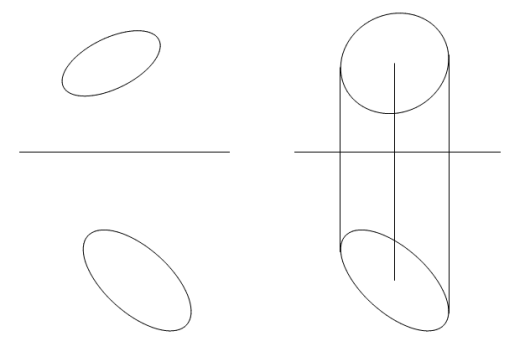
Figure 1 — Reduction of projections to the relevance
The main condition for compliance is that any point on the frontal projection should be reflected in the horizontal projection, and vice versa.
To reconcile the projections user should chose "main", under which second will be transformed . In the case of two ellipses, enough to combine their points for the X and change the length of the axes so that their projections on the X axis were equal. The algorithm is shown in Figure 2.
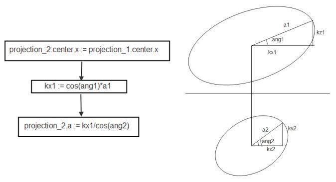
Figure 2 — Algorithm of combining ellipse projections
Solution of the main problem, building 3d-model of the ellipse, is reduced to finding a life-size axes of the ellipse, the construction of the ellipse at the null point, transfer and rotation.
Construction of revolution surfaces
Using these basic objects, like a line and an ellipse, as the geometric determinant, you can specify some surface of revolution — the cone and cylinder.
Geometric determinants of the cone are its base and top. The system allows to construct cone through the provision of projections of its determinants in the drawing. In the 3d-stage cone described by the wire-frame model, which shows a curve of the base and four generators of the lateral surface.
Figure 3 shows the solution of the problem of cone sections finding.
Optional mode helps visibility of solution, projections of the cone are displayed on the projection plane .
Figure 3 — Cone section finding
(animation — size: 560 x 480 px, 49.1 kb; number of frames: 12; delay: 1sec; number of cycles: 1)
Conclusions
Developed library can be used as a basis for educational systems for disciplines that relate to descriptive geometry and computer graphics.
Class hierarchy realizes the possibility of graphic objects constructing in interactive mode using intuitive tools and operations. With its help, you can create a full graphical environment with hot-pluggable architecture. A set of modules for work with 2d and 3d scenes, data storage and mathematical calculations can be modified and used for geometric modeling system design of any application, due to its versatility.
Literature
- Карабчевський В.В. Засоби зв’язку між операціями над двовимірними і тривимірними моделями. // Наукові праці Донецького національного технічного університету. Серія Інформатика, кібернетика та обчислювальна техніка, випуск 93. — Донецьк: ДонНТУ. — 2005. — c. 41-46.
- Дерябин Н.Б., Денисов Е.Ю. Объектно-ориентированная инфраструктура систем компьютерной графики. // Материалы 11-го научно-практического семинара «Новые информационные технологии в автоматизированных системах » — М.:МГИЭМ. — 2008. — с. 10-15.
- Вельтмандер П.В. Учебное пособие «Архитектуры графических систем» - (Учебное пособие в 3-х книгах) Книга 3 — Новосибирский государственный университет. — 1997. — http://cylib.iit.nau.edu.ua/Books/Graph/Study/3d-course/kg01.htm
- Муниципальная ГИС для российских условий: недорогие масштабируемые решения на стандартном ядре // Журнал «САПР и графика» — [электронный ресурс]: http://www.sapr.ru/Article.aspx?id=7218
- Особенности внедрения на предприятиях и методы интеграции CAD/CAM/PDM/FRP/MRP/MES/PLM- и ERP-систем // Журнал «САПР и графика» — [электронный ресурс]: http://www.sapr.ru/Article.aspx?id=18851
- Карабчевский В.В. Компьютерные технологии в преподавании графических дисциплин для специальности «Программное обеспечение» // Труды международной научно-практической конференции «Эффективность инженерного образования в XXI веке». — Донецьк: ДонНТУ. — 2001. — c. 260-267.
- Карабчевський В.В., Хлепітько І.В. Засоби розробки систем геометричного моделювання // Наукові нотатки. Міжвузівський збірник (за напрямом «Інженерна механіка»). Випуск 22. Частина 1. «Сучасні проблеми геометричного моделювання» (квітень, 2008). — Луцьк. — 2008. — c.133-137.
- Бурчак І.Н., Величко В.Л. Програма супроводу дисципліни «Нарисна геометрія» для використання в системі дистанційного навчання // Наукові нотатки. Міжвузівський збірник (за напрямом «Інженерна механіка»). Випуск 22. Частина 1. «Сучасні проблеми геометричного моделювання» (квітень, 2008). — Луцьк. — 2008. — С. 45-50.
- Роджерс Д., Адамс Дж. Математические основы машинной графики: Пер. с агл. — М.:Мир. — 2001. — с.310-340.
- Голованов Н.Н. Геометрическое моделирование. — М.: Издательство Физико-математической литературы. — 2002. — c.105-121.