|
Content
Introduction and actuality
Presently practically there are not the systems, providing like the digital testing the automatic construction of tests for analog and analog-digital (AD) devices on their structural or functional description. The existent systems are called only to help the diagnostician of high qualification, so that tests are built practically by hand coming from thorough knowledges of diagnostician about skhemotekhnikі and functions of object of diagnostics (OD). A problem is aggravated also that tests, hand-generated, are uneffective for the industrial testing of AC-devices on an accessible test equipment and for adaptation to this equipment they have to be built anew, again by hand. [2]
Traditional approach of construction of tests for AC-devices is based on the functional testing on the basis of specifications of OD. Thus a diagnostician supposes usually, that in the process of diagnostics a various control-diagnostic apparatus will be accessible (KDE). Large number of specifications, high cost of KDE and requirements of high qualification, produced to the personnel, and also a process over of diagnosticating, attended with the large number of hand operations, is brought to the low degree of automation and in final analysis to high costliness of traditional approach. The increase of complication of modern AC-devices caused up-integrating AC-IC and by complication of co-operation of their analog and digital knots along with diminishing of correlation of this complication to the incurrence of conclusions AC-IC, substantially aggravates this problem and compels scientists and workers-diagnosticians to search new approaches of testing of AC-devices.
Thus, see that task of search and debugging, analog and AC-devices every day becomes more claimed. Therefore theme of this master's degree work, directed for development and research of methods and structures of vehicle analysis of analog test reactions on a base FPGA, as to one of tasks of the analog testing, is actual.[2]
Purpose and tasks of master's degree work
The purpose of work is automation of process of analysis of test reactions of analog devices. For achievement of the put purpose the followings tasks are in-process put:
• research of existent methods and systems of diagnosticating of AC-devices and analysis of their test reactions in particular;
• development of methods and fpga-structures of analysis of analog test reactions;
• development and research of experimental subsystem of analysis of analog test reactions on a base FPGA.
Supposed scientific novelty
The supposed scientific novelty consists in development of method and architecture of analyzer of analog test sequences on a base FPGA with the purpose of providing of possibility of testing of fast-acting AC-devices. Expected that the developed subsystem will provide a high fast-acting, compactness, flexibility and universality, and also low cost. [9]
Types of the analog testing
We will consider the basic types of testing of analog charts.[1]
The own set of specifications has every class of analog chart (ADC, DAC, filter, chain of phase synchronization and so on). For each of them already there are acceptable functional tests for the test of pre-production model and test sets minimized on length for the tests of batch production. But there are not universal tests for verification of descriptions of charts. Select structural and functional analog tests.
A basic difference between them consists of origin of disrepairs and design procedure.[1]
A functional test supposes often, that components are defective and generates a defect list, using catastrophic and self-reactance disrepairs. For the structural testing statistics of production disrepairs are used.
Testing of analog charts on purpose can be divided into the followings three categories:
• the removal of descriptions of chart for determination whether satisfies it is specifications;
• diagnostics for determination of reason of disrepair, when a chart does not pass a test;
• factory tests, conducted for verification of large volumes of linear and analog-to-digital charts.
In same queue tests are subdivided into the followings kinds [1]:
• tests, based on a specification - generated directly from the specification of chart, without the use of models of analog disrepairs. This approach easily adapts oneself to the wide spectrum of charts. However at the use of plenty of specifications testing becomes dear enough. A test sequence can be brief by the exposure of dependences between specifications and casting-out of unnecessary tests.
• structural tests, built with the use of models of disrepairs - used for the exposure of certain type of the designed disrepairs. It allows to divide the set of analog tests into groups on the degree of coverage of disrepairs, and a test set can be ranged thus. It enables to shorten length of test sequence due to that a test which covers disrepairs already discovered previous tests can be throw-away.
Complications at testing of analog signals
At testing and exposure of disrepairs of charts there are some complications, related to the technological process, by measuring errors et cetera The basic are below resulted from them:
1. Complication of design of disrepairs
Difficult relations have analog charts between entrance and output signals. Many analog charts are the nonlinear systems, for example, MOP-tranzistor, in-use as a strengthener. The values of parameters of chart differ from each other even in good charts. The use of the determined models is uneffective for analog charts.[6] Thus, a signal is accepted by a basic value and the range of possible deviations is selected from a basic value. A design and measuring of inaccuracy and error at planning of the integrated circuits is determined the possible rejection of value of signal. Finally, the statistical distributing of analog disrepairs, as a rule, is not known with sufficient exactness, exactly to define the disrepair of coverages from a test set. There is possibility that analog charts, containing catastrophic disrepairs will pass the production testing.[1]
2. Design errors
The expected values of signal of analog chart settle accounts on the basis of design, exactness of which is limited exactness of numeral values, in-use in the algorithm of design, also a design supposes assumptions, touching exactness of peripheral analog devices. In addition, a design process results in the receipt of the best results on establishment of range of different values.[1]
3. Errors of measurings at testing
Errors of measurings at testing of analog charts arises up from displacement of analog signal, influence of loading of measuring probe on the conduct of analog charts, and also resistances of probe. In addition, casual noise is a problem, therefore analog proof-of-concept devices are limited in a carrying capacity and exactness of measurings. For analog-to-digital microcircuits, sending of values of internal analog signals to output ports can change a signal and work of chart on the whole.[1] The capacitive couplings between high-frequency digital signals and analog signals cause the additional hindrances of analog chart. The analog testing must create a difference on an analog output between in good condition and defective devices, which lies outside test instrumental and automatic proof-of-concept equipment errors.[6]
4. Problems of access at a design
The designed chart is a set of difficult and inaccessible internal component, that limits the use of ordinary analog automatic proof-of-concept equipment.
5. Errors of production process
The different parameters of devices in large production of the integrated circuits volumes submit the statistical laws of distributing. This variety of process can largely influence on the values of parameters of component.[1] There are methods analog design and configuring of charts, to take to the minimum influence of temperature and gradient of diffusion on arrangement of charts. The presence of self-reactance errors influences on a change the cost of component. However much literature on the analog testing also describes the change of data-outs, for example change of amplification of strengthener factor. Both kinds are correct, and sense will be clear from a context. For analog devices plural self-reactance disrepairs (with participation a few insignificant changes of component) the more than anymore size of one disrepair or critical disrepair.
6. Informative stream
It is difficult to test a chart by the individual testing of its subcharts. We will consider the case of analog chart with two cascades of S1 and S2, each of which has one entrance both one output and transmission functions on tension of N1 and N2. S1 and S2 can work wrong when tested individually from imperfection of production process which distorts their transmission functions. However, when cascades unite together can happen so, that distortion in N1 is compensated distortion in N2, which in a manner can be the inversion of distortion of N1. Consequently combination of cascades of S1 and S2 actually works correctly. And vice versa, on separateness correct analog subcharts at connection form a wrong chart.[1]
Content
Functional testing with the use of DSP
Presently practically all analog charts are tested with the use of CASS of control (ASK) built on a base DSP. Information ASK in place of the use of the real analog measurings instruments, execute their emulation on the basis of fast Fourier transformation (FFT) and discrete transformation of Fourier (DPF), in order that to decrease a measuring error and remove undesirable time of establishment of signal at testing.[1]
On a picture 1 a traditional analog is presented ASK. It is needed to pay attention, that it does not have facilities of synchronization between the blocks of generation of influences and analysis of reactions. On a picture 2 presented ASK on a base DSP, which has the proper synchronization and consists of ACP, DAC, to memory for storage of influences and reactions, DSP, which is managed programmatic. DSP can emulate the wide set of measurings tools. Instruments now are podprogrammy which process vector of numeral values. A vector can be a set of selections of signal, frequency spectrum et cetera A specialist on testing creates the set of vectors as test signals. The synthesizer of signals gives these the vector on DAC the output of which is connected with a reconstruction filter for the receipt of continuous signal with the limited bar of key-in. The got signal is given on UUT which reactions are taken off from. Diskretizator of analog signals executes digitising of the taken off reactions with the use of high-speed ACP and saves selections in OZU. When an analog-to-digital chart comes forward as UUT, signals from the outputs of digital part are written down in entrance memory, and tests for digital part are given on the object of diagnostics (ODES) from output memory.[1]
On a picture 3 the process of synthesis of analog signal is represented, and on a picture 4 process of digitising.
 Picture 1 - the Traditional analog ASK [1]
Picture 2 - Analog ASK on a base DSP [1]
Picture 3 - Synthesis of analog signal [1]
Picture 4 - Digitising of analog signal [1]
Advantages ASK on a base DSP
• Exactness. ASK on a base DSP practically always possess greater exactness, what analog instruments, because error in the set of selections of signal considerably less than after digital treatment, what error of individual selection. Aiming, noise and rejections of signals considerably grow short in dsp-testers, because an analog signal is digitised on the earliest stage. The senescence of components of tester and temperature effects is caused by considerably less problems, because digital komponenty save the descriptions better, what analog.[1]
• Speed.DSP-tester can get the set of selections from ODES for one period of selection, and further using DPF and FFT to execute above him the different measurings by emulation of instruments. For implementation of the plural measurings a DSP-tester is considerably more effective, than analog, in which it is necessary to execute the plural measurings. Also in a DSP-tester temporal charges absent on establishment of signal in a filter, which are in an analog tester.[1]
• Simplicity of the use. Because a tester is digital, easily to repeat testing, execute tuning and save the executed tuning.
• More measuring information. DSP- tester gives additional information together with a measureable parameter, for example, the detector of spades reports not only about the value of peak but also about the location of peak in time.
• Size and power.ASK of the general setting on a base DSP less than, cheaper and requires less power, what the proper analog ASK.
Lacks of DSP-based ASK
• They are roads, although a price goes down due to the use of VLSI, and in particular PLIS. Bit, necessary for achievement of acceptable exactness, and requirement on the bar of key-in DSP make them more expensive;
• when it is necessary to execute the only one measuring, analog testers are cheaper cleanly. DSP possess advantage only at the plural measurings;
• flexibility of tool is a problem for an inexperienced operator, because it is necessary to possess practical skills of their use;
• a specialist on testing must know physical and mathematical principles which lie after every test and source of errors.[1]
Realization of algorithms of DSP with a help of FPGA
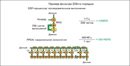
Practically from the moment of the appearance of FPGA positioned as devices, excelling alarm processors on correlation the productivity/price. At the same time known, that programmable microcircuits can not compete with ASIC (specialized for the decision of concrete task the integrated circuit (IC)) at price and clock rate.[3] On a picture 3 distinctions are illustrated between an alarm processor and FPGA at implementation of operation of digital filtration.
Picture 3 - Implementation of digital filtration in an alarm processor and FPGA [3]
On this picture evidently, that, although an alarm processor, created on comparable technology, possesses more time high-frequency on the average, the unique stream of execution of commands of obuslavlivaet the sharp diminishing of incurrence of operations (if under a «operation» to understand all sequence of increases and additions, required for realization of all filter or other algorithm). At the same time FPGA fully can provide odnotaktnoe execution of all operations, using a parallel calculation. The presence of large number of blocks of DSP, executing an increase with an accumulation is instrumental in it, obviously. Unhardness to notice that for the effective use of this advantage it is necessary to be oriented on algorithms and methods, implying rasparallelivanie of operations are filters of high orders, fast Fourier transformation, veyvlet-analysis etc.[3]
In addition, important advantage of FPGA is their ability to provide not simply high-rate of treatment, but yet and continuous processing on stable speed.
A processor kernel can execute organization of interface, tuning, monitoring, load of coefficients and other operations, realize which vehicle too difficultly. Thus the unique processor kernel can provide a management a few hundred dsp-blocks PLIS, which constantly execute treatment of incoming stream even without participation of processor.[3]
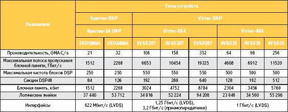
Table 1. Technical descriptions of devices of FPGA Xilinx, oriented to digital treatment of signals [3]
Job performances (in the moment of writing of abstract of thesis)
In the moment of writing of abstract of thesis the followings results were got:
• The review of existent methods of testing is executed;
• on the basis of technical descriptions and on correlation a price\quality was chosen element base for realization of analyzer of analog test reactions;
• Researches are conducted and the experimental device of selection of analog test reactions is developed by the debugging FPGA complex; Presently conducted research on the increase of fast-acting of device of selection.
Conclusions
It is possible to draw conclusion on the basis of foregoing material, that:
• development and research of methods and structures of vehicle analysis of analog test reactions is utterly actual;
• the formulated tasks will allow to attain the put purpose;
• on the basis of the executed review of existent varieties of testing of analog and AC-devices for research, testing was chosen with the use of DSP;
• for the construction of tests and analysis of the got test reactions the optimum class of catastrophic and self-reactance disrepairs was chosen in this work;
• as hardware representation the debugging FPGA complex Spartan-3e was chosen.
List of the used literature
1. Agrawal V.D. Essentials of electronic testing for digital, memory and mixed-signal VLSI circuits / V.D. Agrawal, M. L. Bushnell // Boston: Kluwer Academic Publishers, — 2000, 650p.
2. Bapiraju Vinnakota. Analog and mixed-signal test / Bapiraju Vinnakota // Prentice Hall PTR, 1998. — 261p.
3. Тарасов И. Возможности FPGA фирмы Xilinx в задачах цифровой обработки сигналов [Электронный ресурс] Режим доступа: http://www.kit-e.ru/articles/plis/2007_5_68.php
4. Тарасов И. Сравнительный анализ архитектуры основных семейств ПЛИС FPGA фирмы Xilinx [Электронный ресурс] Режим доступа: http://www.kit-e.ru/articles/plis/2005_6_96.php
5. Давыдов П.С. Техническая диагностика радиоэлектронных устройств и систем / П.С. Давыдов // М.: Радио и связь, 1988. — 256 с.
6. Зинченко Ю.Е. Проблемы зондового поиска неисправностей и пути их решения / Ю.Е. Зинченко, А.М. Козинец, К.Н. Жилин // Сборник трудов Донецкого государственного технического университета. Серия: Информатика, кибернетика и вычислительная техника, выпуск 6. — Донецк: ДонГТУ, 1999.— С. 212—217.
7. Zinchenko Yuri E. Computer-aided design and hardware description languages / Yuri E. Zinchenko // Сборник трудов Донецкого государственного технического университета. Серия: Проблемы моделирования и автоматизации проектирования динамических систем, выпуск 10. — Донецк: ДонГТУ, 1999.— С. 210—216.
8. Суворова Е.А. Проектирование цифровых систем на VHDL / Е.А. Суворова, Ю.Е. Шейнин // СПб.: БХВ-Петербург, 2003. — 576 с.
9. Зинченко Ю.Е. Синтез оптимальных структур асинхронных сигнатурных анализаторов / Ю.Е. Зинченко // Сборник трудов Донецкого государственного технического университета. Серия: Информатика, кибернетика и вычислительная техника, выпуск 6. - Донецк: ДонГТУ, 1999.— С. 186—191.
10. Поляков А.К. Языки VHDL и VERILOG в проектировании цифровой аппаратуры / А.К. Поляков // М.: СОЛОН-Пресс, 2003. — 320с. |