
2. Purpose and objectives of research
3. Flowsheet primary cooling of coke oven gas
5. Characteristics of working mediums
6. Effect of degradation characteristics on the process of heat transfer in object
6.1. Theoretical foundations of heat transfer
7. Methods of prevention of sediments
Safe and stable operation of the primary gas cooler is mainly determined by further processing line chemical coke production plants. Analysis of the possible risks of breakage of the primary gas cooler shows that a major failure of the system is the degradation of the working surfaces.
The whole volume of the coke oven gas from the coking chambers goes to primary gas cooler, which, due to heavy load on them rapidly degraded, which in turn affects the overall manufacturing process and in conjunction with high fire and explosive characteristics of the coke oven gas can cause emissions and accidents. The consequence of this problem is not only the deterioration of the equipment, but also change a design scheme of tubular space and process gas cooling as a whole.
Purpose: determine a combination of factors that affect the safety of the primary gas cooler.
Objectives: To analyze the rates of adhesion of salts of scale and corrosion on the tubular surface of the primary gas cooler, to consider their joint effect on the the process of heat transfer between the coke oven gas and ammonia‐tar water, to develop a mathematical model of the degradation process of the primary gas cooler.
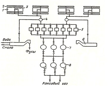
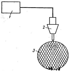
Direct coke oven gas with a temperature of 650 — 750 ° C out of the chambers of coke oven batteries 1, tap the gas while it cooled ammonia‐tar with water to a temperature of 85 ° C by the armature, consisting of a standpipes, gas collector 2 and C / O pipelines 3. The cooled coke oven gas with water and ammonia‐tar pitch goes to separator 4, which is separated from the gas water and pitch.
Water and pitch comes in a mechanized brighteners 6 for settling from separators and coke oven gas — in the primary gas cooler 5. After cooling, the coke oven gas is cleaned of fog pitch in electrostatic 7. Blowers 8 exhausting coke oven gas from the coking chambers and transport it through the apparatus for cooling and product recovery. Primary gas cooler typically include parallel, since the parallel connection of the hydraulic resistance is much lower than sequential. To increase the heat transfer coefficient is sometimes used a mixed series‐parallel connection of refrigerators [1].
Technological scheme of the primary cooling gas is shown in figure 1.1.
Volume of the coke oven gas decreases during cooling, condensate of water vapor and pitch. This will reduce productivity and consumed power blowers for transporting coke oven gas, reduce pollution of pitch pipelines and apparatus for product Recovery, improve the quality of ammonium sulfate and save the properties of absorbing oil of the benzene separation due to reduction of pollution of their pitch
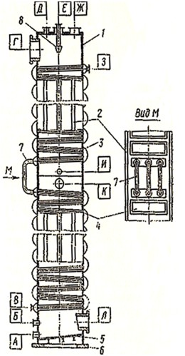
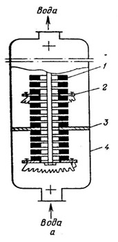
Cooler with a horizontal pipe is shown in (Fig. 2.1). Refrigerator with a horizontal pipe is shown in (Fig. 2.1). Cooler body 1 has a rectangular cross‐section to the 2 vertical walls which flare fixed pipe 3. Shell wall reinforced ribs 2. Pipes divided into separate bundles, which are connected with a removable lid 4. Pipes are located in several extended pitch (82mm). Sparse tube bundles reduces the hydraulic resistance from the gas flow.
The lower part of cooler is flat bottom 5, tilted at an angle of 3 — 4 ° for easy delete of condensate. Enclosure mounted on reinforced concrete foundation support 6. For the comfortable transportation, cooler height is divided into 4 sections, each of which, after build tested hydraulically and goes to the assembly site in assembled form. Sections are connected to each other by welding. Beams sections are connected with transition elbows 7.
Coke oven gas is included in the fitting Г of the cooler, moves downward in the intertube space and exits through the fitting Л Water is pumped from the bottom of fitting В, successively passes all the bundles of pipes, fitting З and gravity is directed to a cooling tower.
As pipes are tilted by 1 ° to the horizon, the condensate formed during cooling of coke oven gas, flows along each tube, and the whole top to bottom, and flushes sediment naphthalene. From the of the cooler condensate extracted through fitting A. In addition to flushing pipes provided supply fitting E ammonia‐tar hot water spray nozzle 8 and in the fitting И the hot pitch which is a good solvent for naphthalene. When steaming steam is fitting Б for service and repair of of the cooler meant hatches J, K and Л. When steaming and blowing of the cooler air vent gas is used Д [2].
The advantages of coolers with horizontal pipes are:
Disadvantages of the cooler with horizontal tubes:
A mixture of vapor and gaseous products of coking, evolved from the coke oven chambers in gas collector, forming direct coke oven gas. It contain the following amounts of chemicals products, g/m 3: water vapor (pyrogenetic and water of the charge) — 250…450; steams of the pitch — 80…150; benzene hydrocarbons — 30…40; ammonia — 8…13; naphthalene — до 10; hydrogen sulfide — 6…40; hydrogen cyanide — 0,5…2,5. In addition, in the direct coke oven gas contains carbon disulfide(CS2), seroksid carbon (COS), thiophene (C4H4S) and their homologues, light pyridine bases (0,4 — 0,6 г/м3), phenols [3].
Fluctuations in the composition of coke oven gas are defined: the difference as of the charge; coking temperature conditions, the state of laying ovens and hydraulic regime; completeness load coking chambers with the charge. The composition and output of chemical products of coking are heavily dependent on the operating mode of heating coke ovens and, in particular, the temperature of coking process, especially the temperature in space coke chambers: the higher it is, the more volatile products of pyrolysis is coke.
Quality of of technical water used for cooling in PGC, should be characterized by the following indicators: hardness is temporary, mg / L, no more — 3; content of suspensions, mg / l, max — 30, the temperature before to the coolers 25 — 27 ° C. The temperature of the heated technical water after coolers should not exceed 45 ° C [4].
The main process in primary gas cooler — primary cooling gas — performed through a process of heat transfer between the coke oven gas and technical water through a cylindrical wall. As a result operation of the equipment appear degradation processes associated with the sticking of scale on the inside surface of pipes and corrosion, which in turn changes the pattern of heat transfer.
Heat transfer — transfer of heat from one substance to another. The substances involved in the process of heat transfer are called coolants. Hot coolant — a substance with a higher temperature, which in the heat exchange process gives off heat, and cold coolant — a substance with a lower temperature, perceiving heat.
The transfer of heat through the wall of coolants do not mix, and each of them moves on a separate channel; surface of the wall separating the coolants used for heat transfer (heat exchange surface). The transfer of heat from one object to another is by conduction, convection and radiation. Conduction heat transfer performed by transferring the heat from direct contact of separate particles of the object. The energy is transferred from one particle to another as a result of the vibrational motion of particles, their movement relative to each other.
Heat transfer by convection is only in liquids and gases by moving their particles. Moving of particles caused by movement whole mass liquid or gas (forced or forced convection), or the difference density of the fluid at different points in the volume caused by irregular distribution of temperature in the mass of liquid or gas (free or natural, convection). Convection is always accompanied by the transfer of heat by conduction.
ПTransferring heat radiation is through the transfer of energy in the form of electromagnetic waves. In this case the thermal energy is converted into radiant energy (radiation) which passes through space and again turns in heat by absorption of energy to other object (absorption). Considered types of heat transfer rarely in pure form, they usually accompany each other (complicated heat exchange). In primary gas cooler is the process of thermal conductivity [5].
The heat equation for the steel heat flow through a cylindrical one layer wall looks like this:
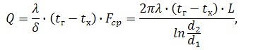
But in conditions of heat transfer equation takes a different form due to degradation processes.
Degradation of the primary gas of the cooler is combined action of 2 factors: corrosion and scale pipe, which leads to a change in the heat and pressures on the pipes of the primary gas of the cooler.
Formed substance is called the scaled layer when its thickness reaches a size that cause dangerous overheating of the metal walls or the presence of these substances reduces the economy operation of the unit. This layer is formed from dissolved or suspended in water, ammonia‐tar compounds. Scale is formed by the interaction of water or chemicals attending in it with a heat transfer surface of the metal, as well as a result of separation of different dissolved substances when heated. These are the alkaline earth metals, consisting of the compounds of Ca and Mg. At the same time depending on the anion component of the calcium sulfate scale divided into (СаSО4), silicate (СаSіО3), carbonate(СаСО3) and phosphate [Са3(РО4)2]; magnesium scale classified into hydroxyl [Мg; Мg(ОН)2] and phosphate.
To cool the coke oven gas in primary gas refrigerator is used ammonia-tar water with the following characteristics: рН 6,5 — 8,7; common hardness: 6,4 — 9,0 mg/kg; calcium hardness of water: 3,6 — 6,2 mg/kg; magnesium hardness: 2,4 — 4,0 mg/kg; alkalinity: 4,2 — 6,0 mg/kg; content Cl: 64 — 92 mg/kg; content SO42−: 164 — 394 mg/kg. The vast majority of the water calcium content usually exceeds the magnesium content. For magnesium base scaling is magnesium hydroxide, which has low solubility, whereas calcium hydroxide has a greater solubility and is not сreate scale.
Rate of formation of calcium and magnesium scale, significant and concentration dependent salts and magnitude of local heat load of heating surface. Cooling water in primary gas cooler the following requirements:
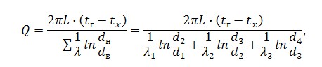
Thus, sediments of scale and growth of corrosion on the pipe wall heat conduction equation will have a different form — the heat conduction equation for steel heat flow through a multilayer cylindrical wall :
The physical methods include methods to prevent sediments, not related to chemical use: magnetic and ultrasonic.
Water is passed through magnitovody, the form and dimensions of which depend on the design of the apparatus, the process conditions and properties of the medium. In this case displaced hydration and acid‐base balance, changing pH, strength, electric conductivity, magnetic susceptibility, aggregate stability and other properties of water‐dispersed systems.
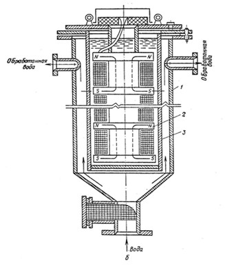
The main factors influencing the effectiveness of the method are the chemical composition of water hardness, the concentration of carbon dioxide, the duration of treatment of water by a magnetic field, the number of poles of the apparatus of the opposite polarity, temperature, flow rate of treated water, the magnetic field and magnetic flux, the frequency of the magnetic field. For implementation of the magnetic method is used permanent magnets (Figure 7.1) and electromagnets (Figure 7.2), fed by direct and alternating current.
To remove scale magnetic field use different machines, different source of the magnetic field. Processing efficiency is significantly reduced as a result of aeration, suspended particles of iron hydroxide. In this regard, the distance from the apparatus to of the cooler choose the shortest. Not excluded the use of intermediate containers and long‐term presence (but not more than 6 — 8 h) treated with fluids at rest prior to their use.
Apparatus for magnetic treatment are mounted vertically, horizontally or obliquely. This ensures laminar processed liquid and prevents the formation air locks. The use of magnetic treatment sharply reduces the amount of repair work.
Are most commonly used generators on electronic lamps and transistors operating in a pulsed or continuous regime.
Scheme of ultrasonic cleaning of the cooler is shown in Figure 7.3.
Slow down the process of scale formation in tube of the cooler space by ultrasound exposure in various ways. On the one party and arising ultrasound is disturbed crystallization kinetics in boundary layer. On the other part, a significant portion of ultrasonic waves at the interface creates a crystalline bond alternating efforts. Under the influence of these efforts, the strength of the crystal is broken ties with the further formation of cracks. Scale is by ultrasound action flakes and falls in form of crusts [8].
For prevent sediment used chemical methods: pH adjustment of recycled water by acidification or partial softening, phosphate, inhibition. The method of processing recycled water is selected depending on the composition of feed water, structural and technological parameters of of the cooler.
Recycling water supply system is purged to reduce the carbonate hardness, which slows down the process of crystallization of calcium carbonate in the water. Acidified water to reduce it ion concentration НСО−3 by increasing the ion concentration Н+, which interacts with НСО−3, forms carbon dioxide and water. Increasing the concentration of hydrogen ions is achieved by introducing in the cooling water solution of sulfuric acid.
Phosphating of recycled water can slow the process of crystallization of calcium carbonate to soften and remove the scum. For this most common of the reagents were sodium hexametaphosphate and sodium tripolyphosphate, and trisodium phosphate and superphosphates. When phosphatizing cooling water is chlorinated it periodically. For prevent the formation of deposits in accordance with building codes P — 31 — 74 provides for stabilization treatment of recycled water by adding in it hydrochloric acid, sulfuric acid, or phosphates.
For reduce the salt deposits have successfully used the inhibition of circulating water. Optimal flow inhibitor is 50 — 100 mg/l, while the amount sediments in the pipes of the cooler is reduced by 60 — 95%. Maximum allowable concentration of inhibitor in water is 0,12 mg/l. However, the inhibition of circulating water contaminated with suspended solids sediment, so the use of inhibitors, it should be filtered. To do this, apply granular filters (grain size 0,5 — 1 mm, the height of transfer layer 1 m), which provides effective cleaning of recycled water from suspended solids.
Also apply complexones class poliaminopolicarbon acids — derivatives α‐amino acid containing molecule, not less than two metilcarboksil groups — СН2 — СООН, bound aliphatic or aromatic radicals. Their distinctive ability — the ability to form with different cations durable water‐soluble compounds that help keep the salt in the bound state, and exclude them from falling on the tubular surface of the cooler.
Technological methods include selection of the optimal speed of the process streams. For reduce the accumulation of sediments establish a speed of move of coolant in which the suspended particles would be entrained flow. This rate depends on the shape, size, density and chemical composition of the particles. Used as methods to improve the surface condition of pipes (roughness, adhesion). For increase the resources of the tube bundle is used anti‐corrosion coating. As the coatings are often is used pitch, furylic and bakelite paints, fluroplastic, aluminum, zinc, chromium, nickel, glass‐enamel coatings with high corrosion resistance [9].
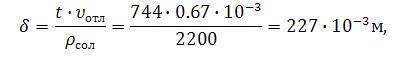
Analysis of available data shows that the corrosion activity skale circulating water Avdeyevka coke plants is much higher than the level required. Speed of scale sediments 0,67•10−3 kg/m2 •h; corrosivity 0,5•10−3 kg/m2 •h.
In the analysis of degradation effects was identified that instead of a single‐layer metal pipe wall is formed of 3‐layer wall:
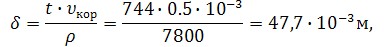
For its consideration of a change in the heat for service life the primary gas of the cooler was proposed to calculate the change in wall thickness, taking into account speed of scale sediments and corrosivity for the month. Then the thickness of the scale will be:
Similarly, we consider increase corrosion layer:
Also introduced in the calculation of the following data: λ = 47 W / m •K — thermal conductivity of steel, λ = 6,9 W / m •K — thermal conductivity of the salt. As change in thermal conductivity is an average of 0.3% for each year of operation due to the aging of the material [10], this factor accounted for an amendment to the calculation of thermal conductivity for corroded metal layer.
Based on these data in the program LabVIEW modeled after the process of the upper section of the primary gas of the cooler (since the activity of scale and corrosion in it is the highest) for 180 months (15 years) with cyclesFor Loop и Formula Node with the condition that at 1 month cleaned pipes from scale, but 10% of the previous treatment can not be removed.
These results show that over the service life of the primary gas of the cooler thermal conductivity for the corroded layer of steel decreased by 4%, the flow section of pipes for water is reduced by 10%, the heat transfer will decrease by almost 11%, and the analysis of the corrosion shows that agressionnoe effects of coke oven gas completely destroy the thickness of metal pipes for a third term of service.
Further development is planned to consider all 3 sections of of the cooler their joint impact on the process of cooling the gas used in computational models of various changes in the composition of cooling water, primary consideration tubular space gas of the cooler, taking into account the degradation characteristics in the stress‐deformed state.
At the time of the site master is not finished yet, so the results are not presented in full.