Specialty "Power Mechanical Complexes ("Computer-electromechanical systems")
1. The problem and its relation to scientific and practical problems.
Changing pressure gas-liquid flow at a height of the lift tube airlift leads to a corresponding change in the hydrodynamic parameters water-air mixture, and, often, and its structure. Improving the energy efficiency of gas-liquid elevators suggests the possibility of quantifying the distribution of power supplied to the apparatus, including height and lifting pipe. Such an analysis must be performed for the characteristic modes of airlift, one of which is the regime of maximum flow. Along with the slug and emulsion, the airlift is possible to realize a ring structure water-air mixture, especially when working at small relative immersion mixer (α <0,2), as is the case, particularly when cleaning sumps skip shafts of coal mines, etc. Therefore, the quantitative analysis of the distribution of the hydrodynamic parameters of the circular water-air flow at a height of the lift tube airlift mode of its maximum capacity is an urgent scientific and practical challenge.
2. Analysis of research and publications.
Analysis of changes in hydrodynamic parameters, mainly the pressure and power, [1, 2, 3] is executed, depending on the gas-liquid flow of compressed air lift. Of the distribution of gas content, density, velocity, gas-liquid mixture and its components, as well as pressure and flow capacities of water-air vertical lift tube airlift in these studies were not considered. A similar problem was solved in [4] for the structure of the slug gas-liquid mixture in the lift tube airlift. However, given the fundamental differences in the physical basis of slug and annular structures of water-air flow [5] and the principles of mathematical modeling of business processes airlifts with these structures [6, 7], we should expect differences in the patterns of change in the hydrodynamic parameters of gas-liquid flows with a ring structure on well-known established laws with respect to the two-phase slug flow in the airlift mix.
3. Formulation of the problem.
For maximum flow regime, as one of the characteristic modes of airlift, to establish patterns of changes in hydrodynamic parameters of the circular water-air flow in a vertical height of the lift tube gas-liquid lift.
4. Presentation of the material and results.
When the ring structure water-air flow in a vertical lift tube airlift will be understood per se, in which the liquid film thickness δ (z) moves along the inner wall and the gas from the droplet and closely related fluid inclusions forms the core of the flow. Gas-liquid flow between the core and liquid film mass transfer occurs due to entrainment and deposition of droplets.
Animated gif 1.1 - start-up airlift (positions: 1 - vozduhopodayuschaya pipe, 2 - Mixer 3 - supply tube, 4 - Lifting pipe, 5 - air purge)
(Number of shots - 21, the number of repetitions is unlimited, the amount of 109KV, created in Easy GIF Animator 2.0)
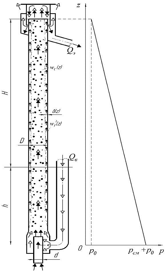
Picture 1.2 - The scheme of the ring structure of airlift water-air flow in the lift tube airlift
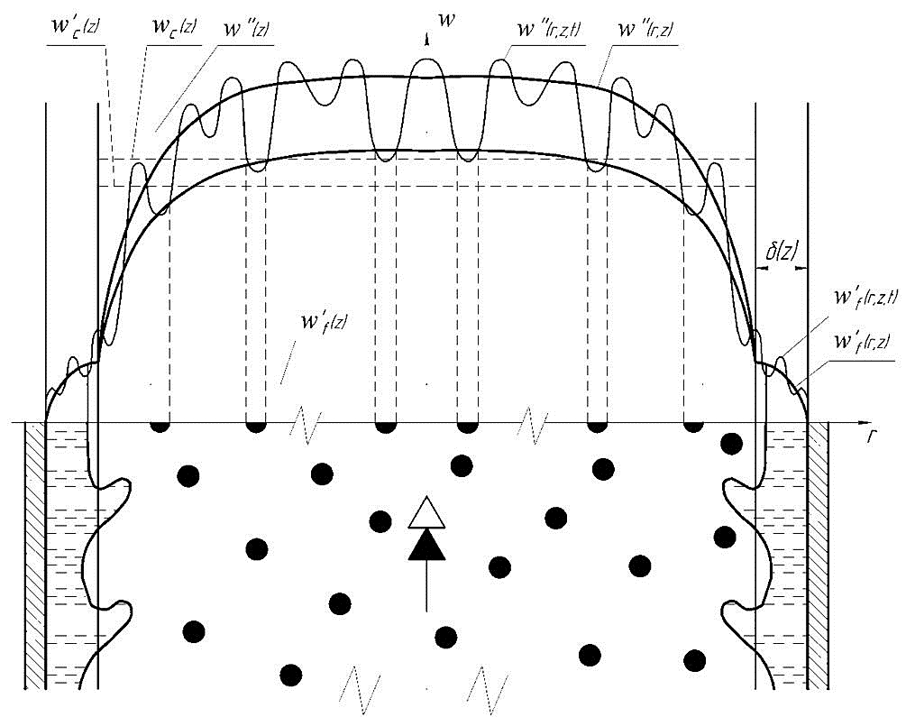
Picture 1.3 - Curves of mean velocity components of water-air flow in a circular pipe lift airlift
Solving a system of equations taking into account the mass exchange between the nucleus and a homogeneous film of the wall of the ring structure of two-phase flow for airlifts to lift pipe diameter D = 20 ÷ 400 mm and lengths of the H + h = 5 ÷ 50 m and the relative geometric immersions α = 0,05 ÷ 0, 20 could not be found. Explain the possible use of a limited range of empirical relationships for determining the droplet mass transfer between the core gas-liquid flow and the wall film. In addition, these relationships appear to have been obtained for conditions different from those in the water-gas-liquid flow lifts. Therefore, the empirical dependence of the intensity of mass exchange between the core and the annular film flow in the airlift require experimental clarification. To be able to quantify the workflow airlift of water-air mixture of the ring structure calculations were performed assuming no mass transfer between the core flow and the wall film and the condition of constant film thickness over the entire height of lift tube.Quantitative calculations using a mathematical model of gas-liquid workflow lift the ring structure of water-air flow were made for airlifts to lift pipe diameter D = 100 ÷ 250 mm and lengths of the H + h = 11,7 ÷ 31,2 m, the geometric mixing dives h = 1, 28 ÷ 4,32 m (relative geometric immersions α = 0,070 ÷ 0,205). The comparison between the calculated and experimentally determined innings airlifts in the optimal mode and the mode of maximum flow in a circular structure of the mixture, and comparing the calculated and experimental flow rate characteristics of the lift with a lifting pipe D = 150 mm, H + h = 11,7 m calculations were performed with both Using a mathematical model with a constant pressure in the mixer given by "r-const», and with a constant geometrical immersion mixer «h-const» and the calculation of head loss in pipe flow by the method used for the nozzles.
Model of "r-const» also used to calculate the hydrodynamic parameters of the circular water-air flow in air-lift with lifting pipe D = 150 mm, H + h = 11,7 m, although the geometric characteristics of the supply pipe is known for the lift (d = 30 mm, l = 460 mm). Application experimentally measured pressure in the mixer, which in the range of flow rates of compressed air has a relatively stable value of PCM = 14.9 kPa.
The deviation of the calculated feed airlifts in the optimal treatment and maximum feed rates of the experimental evidence for the ring structure does not exceed 30%.
Thus, even without the gas-liquid mass transfer between the core flow and near-wall film of the developed mathematical model satisfactorily describes the workflow of a ring structure airlift water-air flow.
Analysis of the distribution of pressure and water-air flow capacity of the ring structure is made on the example of air-lift with lifting the pipe diameter D = 150 mm, a length of H + h = 11,7 m, the flow tube diameter d = 30 mm and length l = 460 mm with a geometric embedding of the mixer h = 2,4 m (relative geometric immersion mixer α = 0,205).
Been assumed validity of the use of mathematical models of the workflow with the ring structure airlift water-air flow in the whole range of changes in air flow, quantitative calculations are made at constant pressure in the mixer "r-const», equal to the experimentally measured RSM = 0.152 kg/cm2 (14.9 kPa .)
In constructing the dimensionless flow characteristics of gas-liquid lift as basic values were adopted cost of air and air-lift supply at maximum feed Qv.maks = 19.2 m3/min (0.32 m3 / s) = Qe.maks 7.20 m3 / h (0,002 m3 / s)
For the first time airlifts to lift pipe diameter D = 100 ÷ 250 mm with the ring structure of water-air flow is shown that the regime of maximum power supply relative to offset losses on the slide is in the range 75 ÷ 95%. The rest of the behaviors of the power expended to overcome the force of gravity compensation and friction losses and acceleration.
For the air-lift with lifting the pipe diameter D = 150 mm and a length of H + h = 11,7 m and a geometric immersion mixer h = 2,4 m at the maximum supply and water-air mixture of the ring structure as an example the values of the hydrodynamic parameters of two-phase flow adjustment Lift the pipe. Volumetric consumption gas content in the range β = 0,993 ÷ 0,994, the true gas content - φ = 0,948 ÷ 0,956. The density of the core gas-liquid flow decreases from ρ = 4,85 kg/m3 at the level of the mixer to 4.21 kg/m3 at the exit of the lift tube, and the rate of homogeneous kernels - increases (from wc = 18,0 m / s and 20 wc = , 7 m / s) at a constant rate of water in the wall film 0.482 m / s due to the absence of mass transfer received approval between the homogeneous core and an annular wall film flow structure and consistency in film thickness at a height of the lift tube. Calculated as the changes of pressure and water-air mixture to power the lift height of the pipe to compensate for gravity, friction, and acceleration, as well as losses due to sliding of the phases.
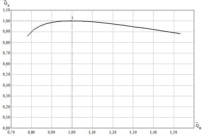
Picture 2 - The dimensionless characteristic of airlift expenditures
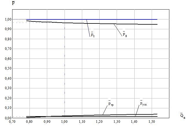
Picture 3 - Changing the relative pressures in the airlift
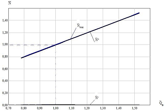
Picture 4 - The change in relative power in the failed airlift
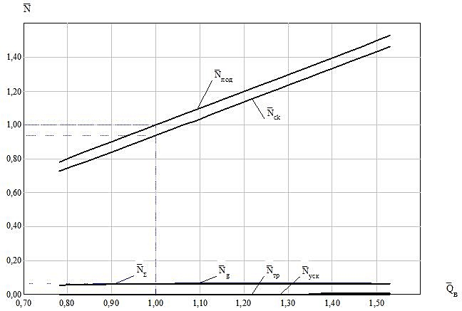
Picture 5 - The change in relative power in the airlift
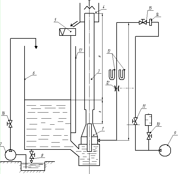
Picture 6 - Hydraulic scheme of the laboratory air lift installation
Laboratory air lift hydraulic circuit is shown in Fig.6. In order to obtain more information about the processes occurring in the airlift when dealing with small absolute and relative dives, all its basic elements (flow and lift tube tube mixer) were made transparent (Plexiglas). The diameter of the lift airlift pipe 3 is 0.14 m, length - 4.67 m
To create a dive airlift used metal tank 6. The water in the tank is fed by pipeline Ø 0,0105 m with a pump 7. Control of immersion mixer airlift was carried out using water-glass 17 mounted on the tank.
As a source of compressed air was turbogazoduvka (No. 9), TG-50-1, 9, with a maximum overpressure 9x MPa. Regulation of compressed air supplied to the airlift of air duct (Item 2) Ø 0,105 m, was carried out with the valve 15 is installed on the duct and the valve 10 for discharge of excess air in the atmosphere.
To measure the flow of compressed air used in the airlift normal diaphragm 12, Ø 67,2 mm with annular chambers. Measurement of differential pressure on the diaphragm and the pressure to the diaphragm was performed using the U-shaped manometer 13, respectively, filled with water and mercury.
Hydraulic scheme of the laboratory air lift installation closed: water, raised by airlift, after the evaporator 4 is sent to a triangular weir 5, and then dumped into the tank.
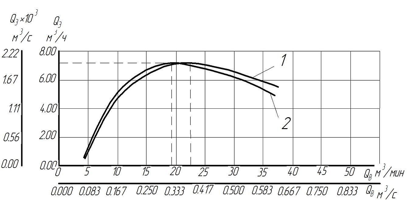
Picture 7 - Flow characteristics of air lift, obtained by the traditional method 1, (QAmax1 = 22.7 m3/min; D1 = 168 mm) by the refined method 2 (QAmax2 = 19.2 m3/min; D2 = 150 mm) H + h = 11, 7 m, α = 0,205
5. Conclusions and directions for further research.
The work associated with the decision of relevant scientific technical problem, which is to improve the energy efficiency of hydro plants to clean mine underground tanks at the expense of rational justification of the parameters of the workflow malopogruzhnogo airlift in view of the frictional forces between the water-air homogeneous core and near-wall liquid film in the ring structure of the water-air flow in a vertical lift the tube, which reduces the power consumption of air lift installation on 12-15%

1. Pirverdyan A Theoretical Foundations of lifting the liquid with compressed air.Azerbaijani oil industry, N1, 1951, pp.16-19.
2. Pirverdyan AM Physical basis of recovery of the liquid with compressed air. Azer-dzhanskoe oil economy, N10, 1951, pp. 4-7.
3. Kutateladze SS, Styrikovich M Hydrodynamics of gas-liquid systems. 2 nd ed., Revised. - Moscow: Energiya, 1976 - 296.
4. Nigmatulin R Dynamics of multiphase Matter. - M.: Science, Ch. Ed. fiz.mat. lit., 1987. - 360.
5. Wallace G. One-dimensional two-phase radiation. Moscow: Mir, 1972. - 440.
6. Armand A. Investigation of the mechanism of motion of two-phase mixture in a vertical tube. In the book.: Hydrodynamics and heat transfer during boiling in high-pressure boilers. Moscow: USSR Academy of Sciences, 1955, pp. 21-34.
7. Investigation of turbulent flow two-phase media, Ed. S Kutateladze, Novosibirsk, 1973. - 315.
8. Markovich, E Education and length of liquid plugs in gas lift wells. Neuftyanoe economy, 1991, N12, p.22-23.
9. Aytemirov Z Some aspects of motion of the structure of cork gas / oil flow. Math. Universities, Oil and Gas, 1969, N8, with. 39-41.
0. Movement of liquid mixtures in pipes / V Mamaev, G Odishariya, Klapchuk O Tochigin AA, Semenov, E Moscow: Nedra, 1978. - 271.
11. V Subbotin, praising J, Mikhailov L, Cronin I, Leonov V Timesnye and structural characteristics gazozhidkostnogo flow in slug flow. Heat energy, 1976, N1, p.67-70.
12. VI Subbotin, praising J, Leonov V The structure of the slug-steam flux. Thermal Engineering, 1977, N7, p.65-67.
13. Gritsenko, A, Klapchuk O Kharchevto Y Hydrodynamics of liquid mixtures in wells and pipelines. Moscow: Nedra, 1994.
14 Kononnenko A Changing hydrodynamic parameters water-air slug flow height of the riser pipe airlift
Access to an electronic resource:[http://visnyk.sumdu.edu.ua/arhiv/2006/12(96)/2_Kononenko.pdf]
Back to top


 DonNTU © 2011-2012