 |
|||
| Abstract | |||
Theme: Increase of metrological reliability of absorbing measuring instruments of methan
|
|
|||||||
 |
|||||||
|
|||||||
|
|||||||
|
|
Русский | Українська | English |
|||||||||||||||||||||||||||||
|
|
||||||||||||||||||||||||||||
Connection with scientific programmes, plans and topicThe Master paper is done within the limits of government budget scientific research topics of the State Institution of Higher Education “Donetsk National Technical University” D–14–07 «Development of operation speed methane concentration measurer for gas protecting system of mines» AimIncreasing of metrological reliability of absorbing methane measurers in mines by means of optico-absorbing method of methane concentration control and compensation of perturbation factors that affect measuring results. ObjectsTo achieve the aims of given work the following objects are stated:
Solution of the above mentioned aims is the basis for development of structural scheme of methane measurement for gas protecting system in mines. Supposed scientific innovation and planned practical results
The basic material of worMethane (СН4) has specific gravity of 0,554. The characteristic features of this gas are burning quality and ability to give an explosive mixture in combination with air. The classification of automatic gas control equipment on the functioning principalAccording to all-Union State Standard 13320—81 [1] depending on the functioning principal (method of analysis) gas analysis non-stop working automatic indicators are divided into: mechanical, sonorous and ultrasonic; thermal; magnetic; electrochemical; ionizating and optical. Indicators of each type are subdivided into some sub-types. Sonorous and ultrasonic indicators can be:
Thermo gas-analysis indicators are subdivided into:
Magnetic indicators are subdivided into:
Electromechanical indicators are subdivided into:
Ionizating indicators are subdivided according decreasing and increasing of ion current. Optical indicators are subdivided into absorptive and emissive. Absorptive indicators are subdivided according to the spectral region where the measuring takes place:
Emissive indicators are subdivided into electrodischarged, fervent and phosphor. Interference refractometers fall into the optical indicators category as well (they are not indicated in all-Union State Standard 13320—81 [1] because of that interferometers were used only as indicators of episodic, but not non-stop functioning indicators). One of the most common and general ways of preparation of multicomponent gas mixtures for analysis is physical division of separate components that is based on their distribution between two phases — motionless and mobile (flowing through motionless). Such distribution method is called chromatographic, and indicators where it is used are called chromotographs. Chromotographs where gas is used as a mobile phase are called autogenous. In autogenous chromotographs for quantitative identification of separate components concentration in analyzing mixture (after their separation) it is possible to use any method from mentioned above, if it provides sufficient sensitivity to controlling gases. Another effective method of separation and analyzing of different substances mixture is mass spectrum method. Analyzing advantages and disadvantages of existing indication methods of methane concentration the optico-absorptive method of measuring has been chosen. Mine indicators based on this method function in infra-red region with the using of optico-sonorous effect [3]. During the explanation of infra-red emission intake the classical theory proceeds from that atoms and gas molecules possess their own vibration frequencies specific for each gas and the intake takes place each time when the vibrating system and decreasing radiation are resonant with each other. Quantum theory explains intake of electromagnetic waves by transformation of atoms and gas molecules from the lower state condition into the higher energy state. However, it is stated that atoms and molecules can take up only strictly fixed specific for this substance discrete portion of energy. The most part of energy that is absorbed by gases transforms into warm [2]. The Bouguer Law sets the connection between the magnitude J of incident flux emission and quantity of energy dJdv absorbed by indefinite thin layer dx of the analyzing gas in the spectral range dv:
where dv is a wave number; К is an entrance coefficient (constant quantity that characterizes the layer intake and that is designed per unit of thickness upon the constant wave number). Entrance coefficient K of frequency radiation is called proportionality constant of the Bouguer Law of intake in differential form:
where dI(l) is decay of the sway intensity radiation I undergone the environment layer of dl thickness. In the case of uniform medium the integral form of the Bouguer Law is of the form of the following:
where I0 and I are radiation intensity before and after passing the layer l thick. The exponent index in the previous formula is regarded as optical depth:
Integrating of this formula on х gives a linear connection variable of passing stream j from absorption coefficient К, layer thickness х and variable of passing stream J0 in the spectral range dv (Lambert’s law):
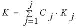
The experimental research [3] of radiant energy intake by the environment which thickness is not the same everywhere has shown that radiant energy undergoes the equal changes only when it meets the equal number of corpuscles that are able to entrap the rays or dissipate them. So not only the thicknesses matter for intake, but the substance mass as well, for the gas that intakes the radiant energy and that is dissipated in almost non-taking up gases where the intake coefficient is in portion to the quantity of intake molecules for the unit of wave path length (or for unit volume), i.e. is portion to the concentration С. According to the Beer’s Law the coefficient K is defined from the following formula for the mixture j of intake gases:
where Кj is the intake coefficient of j component; Сj is the concentration of j component in the mixture. In its turn the formula can be introduced in the following way with the accordance of the mentioned above:
where А is a new coefficient that is not dependent on the concentration and is for the molecule of the intake gas. The development of this method has led to the possibility of fast-operating increase in methane concentration controlling in mines. The review of main components and the general structural scheme of spectral infra-red gas analyzatorLet’s imagine the generalized structural scheme of the spectral indicator:
Figure 1 – The generalized structural scheme of the spectral indicator 1) The source of radiation creates the material medium of useful information that is the radiation stream; 2) Optic passing system forms the stream the radiation source and directs it to the disperse device. In the majority of spectral indicators используются collimating systems are used; 3) The disperse device decomposes the radiation of a complex mixture into monochromatic components. It is the structural element in the optical scheme and it can be inside the optical scheme, i.e. to be interagent in the optical components chain in the optical scheme; 4) Receiving optical system is also referred to the optical scheme components and is aimed for formation of a stream at the receiver that is decomposed into radiation spectrum; 5) The receiver of radiation energy serves for transformation of a signal brought by the stream; (It is necessary to put the device for signal processing in the gap between 5 and 6 as a booster for demodulating and signal filtration in order to allocate information about the environment’s parameters) 6) The registering device serves for signal transformation to the most convenient types spectrum scripts; It should be emphasized that the separate elements of the optical system spectral indicators can be or combined in one device. In addition to the units in the spectral indicators sets there often can be found some additional elements (input choppers, balance gears, auyomatic program control for working regimes, scanning mechanisms, etc.) and adapters for special measuring as well. Development of optical scheme of methane concentration indicatorIn optical gas analyzators auto compensational biradial optical scheme is used for zero stability increasing and for compensation of moisture effect, dust and other factors that are able to intake light. The rays’ intensity is measured in auto compensational biradial scheme where the rays pass the same optical way and the wave length of a measuring ray is in the intake area while the wave length of the other (mounting) is in the area of the identified gas transparency.
Figure 2 – Animation of methane concentration indicator optical channels Animation: Easy GIF Animator, quantity of frames – 6; quantity of repetition cycles– 6; volume – 104 Kb Radiation streams from the indicating and compensational light-emitting diodes come to lenses О1 and О3that in their turn form the direct streams of radiation coming to the open indicating ОК1 and compensational ОК2 optical channels. The coming through the optical channels infra-red streams go to the lenses О2 and О4 that bring into focus direct parallel radiation streams where ФД1 and ФД2 image-storage devices of main indicating and compensational channels are situated. Received signal output ФД1 and ФД2 are stream signals. Their unit values are proportional to the streams of main and compensational optical channels.. It is necessary to mention that dust yielding on the optical elements is one of the most significant problems. It leads to the impairment of transmission capacity of optical components that in its turn leads to decreasing of metrological reliability. The dust filter is used against the dust chinking. It is a pretersonic vibration generator that helps to clean the optical components and provides increase of metrological reliability and device’s maintenance interval. The prototype of this device is the invention by Olympus E-System that protects the sensitive sensor from dust during the photo cameras’ lenses change.
There two main type of dust: dust that is drawn by static electricity and dust that is drawn on the molecular level. Dust that is drawn by static electricity. The majority of sensor scumming is caused by dust particles which size is less than micron and they are drawn by static electricity. Dust itself has positive electronic charge while the sensor has negative charge. As a result the sensor draws dust like a magnet. This type of dust can be removed with the help of ultrasonic wave filter.
ConclusionsModern existing methods and ways for methane concentration control do not provide the necessary fast operating in mines. Using of the optico-absorption method and modern optics and microelectronics will allow creating fast operating indicator with advanced metrological and working characteristics for methane concentration measuring. When writing this autosummary master work was not yet completed. The final completion on December 2012. Literature1. ГОСТ 13320-81. Газоанализаторы промышленные автоматические. Общие технические условия. Введ. 01. 01. 1983 // М.: Издательство стандартов, 1989. – 35 с. 2. Бреслер П.И. Оптические абсорбционные газоанализаторы и их применение. // Л.: Энергия, Ленинградское отделение, 1980. – 164 с. 3. Карпов Е.Ф., Биренберг И.Э. Автоматическая газовая защита и контроль рудничной атмосферы. // М.: Наука, 1984.–285с. 4. Якушенкова Ю.Г. Проектирование оптико-электронных приборов. // М.: Машиностроение, 1981. – 263 с. 5. Нецепляев М.И, Любимова А.И, Петрухин П.М. Борьба со взрывами угольной пыли в шахтах. // М.: Недра, 1992. – 298 с. 7. Вовна А.В.,Хламов М.Г. «Применение оптико-абсорбционного метода для измерения объемной концентрации метана в условиях угольных шахт» Наукові праці Донецького національного технічного університету. Серія: «Обчислювальна техніка та автоматизація» // Донецьк, 2007. – Випуск 13(121). – С. 173 –179. 8. Джексон Р.Г. Новейшие датчики. // М.: Техносфера, 2007. – 384 с. 9. ГОСТ 24032-80 « Приборы шахтные газоаналитические». // М., 1992. – 36 с. 10. Погоржельский Ю.А. Диссертация. «Обоснование структуры быстродействующего измерителя концентрации метана системы газовой защиты угольных шахт» http://www.uran.donetsk.ua/~masters/2004/kita/pogorzhelskiy/diss/index.htm 11. Попов А.А, Шерстнев В.В., Яковлев Ю.П. «Светодиоды для измерения метана» http://masters.donntu.ru/2004/kita/pogorzhelskiy/library/lib5.pdf 12. Трембецкая О. А. Магистерская. «Обоснование структуры быстродействующего прибора для измерения концентрации метана в условиях угольных шахт» http://masters.donntu.ru/2009/kita/trembetska/diss/index.htm
|

 ,
,