
Abstract
Introduction and object of researchesPurpose of the work: to study theoretically and experimentally the ways of management of behaviour of the robot Koala using modelling, connection to personal computer and to create an algorithm of output of optical flow for orientation and avoiding of obstacles by the mobile robot indoors. ⇒ In the project of an off-line control the wheel robot Koala in the environment of closed premises and on open air, it is possible to develop visual perception with which the robot moves in a corridor at the expense of automatic control of its speed and its free space to walls. ⇒ At studying of behaviour of insects their some ways of orientation in space which it is possible have been opened is artificial to recreate in a robotics. For example, winged insects are capable to move quickly in the unfamiliar environment by extraction of the visual information from own movements. This visual information can be used in a robotics as a function of optical flow, that is visible movement of image of objects, and for insects – the contrast functions projected on a retina of an insect. Insects use it to avoid collisions, following on a corridor [1, 2]. Some authors tested wheel robots in which speed in relation to the earth was supervised by comparison of the sums of two lateral OF with reference size (e.g. [8]), but in present work one digital onboard camera is used, therefore the simulated program of navigation will be offered in the future. 1. Short description of the robot KoalaShort description of the robot Koala – the wheel mobile robot of average size. The robot is equipped by two blocks of three lateral wheels, with the maximum speed 0.4 м\с, wheels have radius of 45 mm and are established on axes of 30 cm in length, which management gives possibility of changing of rotation and moving speed of the robot. As they are independent, the robot can turn on a place. The mass takes 3.6 kg (4 kg with the battery). Each engine is equipped by the incremental coding device, reading out 5850 pulsations for turn. With a view of control Koala is provided by processor Motorola 68331@22 MHz. To operate the robot, it is possible to send commands from the remote personal computer through serial port RS232, and the robot answers any action, or sending to data back (reading of coding devices). Engines can be operated directly, regulating a cycle of an applied signal of pulse-width modulation (PWM) each engine, or indirectly through the enclosed controllers of position and speed. Koala is equipped by 16 infra-red sensors, each of which can measure surrounding brightness or affinity to the closest obstacle. But in this work infra-red sensors are not used and replaced by the onboard camera working in function of optical flow. Images from the camera are made through the graphic card connected with the personal computer. The control and visual algorithms are carried out, using language C ++. 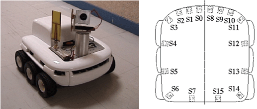
Figure 1 – Photo and scheme of sensors of the robot Koala 2. The equation of optical flowThe optical flow (OF) – is an image of visible movement of objects, surfaces or stage edges, received as a result of moving of the observer (eyes or the camera) concerning a scene. The algorithms based on optical flow, such as movement registration, segmentation of objects, coding of movements and calculation of a disparity in stereo use this movement of objects, surfaces and edges [2]. The methods based on optical flow, calculate movement between two frames taken at the moment of time t and t+δt, , in each pixel, they use private derivatives on time and spatial coordinates. These methods are called as differential as they are based on approach of a signal by a piece of Taylor’s line; thus, they use private derivatives on time and spatial coordinates. 
where Vx, Vy are x and y components of speed of optical flow in I(x,y,t) Thus the pixel in positions (x,y,t) with intensity I(x,y,t) for one frame will be moved on δx, δy and δt. The received equation contains two unknown persons and it can not be unequivocally resolved. This circumstance is known as an aperture problem. The problem is solved by imposing of additional restrictions – regularizing. Algorithms of optical flow not only define a flow field, but also use an optical flow at the analysis of three-dimensional essence and scene structure, and also 3D movements of objects and the observer concerning a scene. The optical flow is used in a robotics in such areas as: recognition of objects, tracking objects, definitions of movement and in robot navigation. The optical flow is used not only for definition of movement of the observer and objects concerning a scene, but also for studying of structure of objects. As, definition of movement and creation of cards of structure of environment, are an integral part of animal (human) sight realisation of this knack by computer means is an integral part of computer sight. However, the problem of methods of finding movement, consists in, whether that in the field of computer sight without the additional information it is impossible to tell: the object moves, and the observer costs on a place, or the object is reposed, and the observer moves [2]. 3. FireWire digital cameraThe digital onboard camera is preferable to the further work at level of a board in full volume 400Мб FireWire the cameras corresponding to specification IIDC for industrial not compressed VGA of reception of the image, created on the basis of a chipset of digital camera Texas Instruments 1394 and PZS-SENSOR CONTROLS Sony®Wfine Fire-i™. For my project the camera of such type has been given by University of Cergy-Pontoise (Laboratory ETIS) in connection with the teamwork with DonNTU. 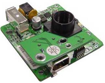
Figure 2 – Fire–i™ digital camera Fire-i ™ digital onboard camera supplies tension FireWire of the tyre of a direct current from adapters or other devices FireWire connected with 6-contact cables. It works with any participant IEEE-1394 PCI or PCMCIA (CardBus) OHCI the compatible adapter or any desktop/portable personal computer or Mac with built in FireWire support. 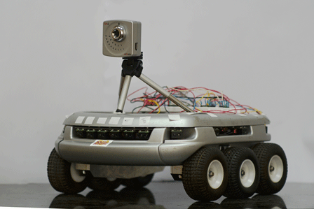
Figure 3 – Robot "Koala" with onboard Fire–i™ digital camera The structure of work of the robot Koala (it is taken from [9], p. 84), which contains the short scheme of interactions between the camera and the robot is presented below:
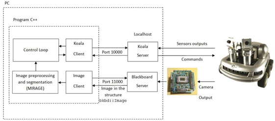
Figure 4 – Block diagramme of the robot Koala 4. Acquaintance with management of the robot Koala in the environment of MatlabFor the purpose of acquaintance with management of robot Koala in the environment of Matlab, the basic functions and commands of regulation of speed, position, acceleration of engines of driving wheels have been used. The establishment of communication of the robot and the computer was made through the standard interface of consecutive data transmission RS232. As a result we have received the diagramme of actuating of wheels with various values of speed and dispersal time on each of them. Also on the diagramme reaction to the additional resistance to movement enclosed to one of wheels is shown. 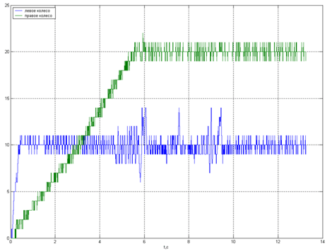
Figure 5 – Acceleration of wheel engines of the robot The program text: 
Animation: 6 shots, duration of each frame – 100 ms, 35,9 KB 5. A demo “Tracking Cars Using Optical Flow” in the environment of MatlabIn the programme Matlab there is a number of demos-appendices in which the optical flow is used for decisions of various problems. Demo–model “Tracking Cars Using Optical Flow” was taken as an example of application of optical flow. As a result very simple experiments for understanding the work of OF which concerns methods of calculation and changes of parametres in model have been made some. But to change parametres it is necessary for each certain case when there are modelling specific goals. The model presented below will be used as a basis for modelling in my work. 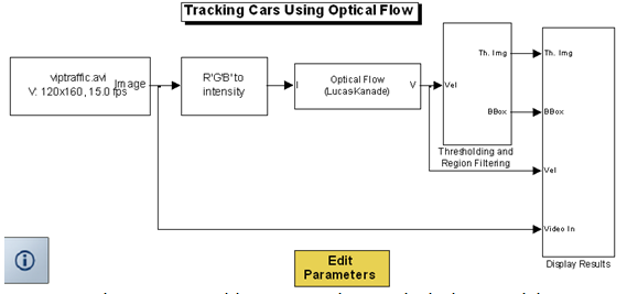
Figure 6 – The Tracking Cars Using Optical Flow model 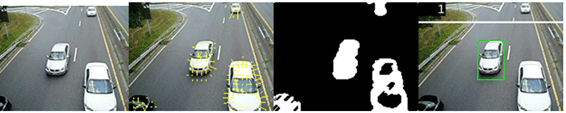
Figure 7 – Images describing optical flow of movement of cars Conclusions and tasks for futureAt the writing of the present abstract master's work is at working out stage, therefore we will express the primary goals of research:
References
|