
Abstract
Content
- Introduction
- 1. Analysis of existing methods of optimization of the elastic pattern
- 2. Analysis of existing structures devices for the grinding of the elastic pattern
- 2.1 Device for the internal and external round grinding
- 2.2 Device for the internal grinding
- 3. Statement of research objectives
- 4. The calculation of dynamic characteristics of electrically operated spindle node
- Conclusions
- List of references
Introduction
In modern industry widespread hard alloys, which belong to the intractable materials. For their efficient processing of diamonds are used, as well as grinding wheels on the metal binder, filled with the electroerosive processing.
Optimization of regimes of processing classic method requires a large investment of time, which may be substantially reduced through the use of a new method to determine the mode, given by the chair of metal-cutting machines and instruments of the Donetsk National Technical University, using the instant limit the cutting ability of the circle, as defined in the grinding of the elastic pattern. Use of a method of location of modes with respect to the current limit of the cutting ability of the circle contributes to the reduction of labour intensity of the search modes and allows you to fully use the cutting ability of the working surface of the circle (WSC).
The relevance of the theme: the study of the cutting ability of the WSC internal grinding of hard alloys diamond circles are absent in the literature that testifies to the topicality of this work.
Object of research: pattern of change of the cutting ability of the surface of the circle internal grinding of hard alloy circles from superhard materials, filled with the the electroerosive processing.
The aim of the work: improving the performance of internal grinding of hard alloys due to the full use of the cutting power of the circle.
Scientific novelty of the work consists in the fact that for the first time will be obtained equations describing the change of the cutting power of the circle with internal grinding the elastic pattern.
The practical value of the work: development of new design of wheelhead, in which at the expense of new structural elements is ensured by the possibility of internal grinding of holes, the radius of which exceeds the course of the front pasterns, as well as the execution of grinding the outside cylindrical surface, preserving the quality of processing and material costs, as well as the receipt of equations, describing the change of the cutting ability of the surface of the circle, which can later be used for optimization of the process of grinding.
1. Analysis of existing methods of optimization of the elastic pattern
Ensuring high-performance machining of various groups of materials subject to receiving the required quality indicators and minimization of the cost of the processing is permanently urgent task, which is constantly solved at the stage of technological preparation of machine-building production.
Mandatory procedure for solving this problem is the search of optimum modes of processing. In respect to the processes of grinding, the most common and one of the most accurate methods, by this time, is a classic experimental-theoretical method of finding mode, which includes the following stages [1]:
- develop a system of equations, describing the technical restrictions on the modes of cutting the requirements of the parts, machine tool and manufacturing conditions;
- mathematical description of the objective function, which is a the purpose of optimization;
- the joint consideration of the technical constraints and the target function and determination on the basis of an optimum mode of grinding.
For a long time at the Department "Metal-Cutting machine tools" of DonNTU studies are related to the study of the following questions:
- determination of the parameters of the grinding process, providing the given roughness of the processed surface [2];
- search allowable value the forces of interaction of the working surface of the circle (WSC) with the surface of the workpiece, in which will not take place of phase-structural changes in the surface layer of the workpiece [3];
- search allowable value the forces of interaction between the WSC with the surface of the workpiece, in which there are no changes of physico-chemical properties of instrumental material [4,5];
- search of the integral technical restrictions on the modes of grinding, providing maximum performance when subject to specified requirements on the quality of processing [4,5].
According to the results of the conducted research has developed a number of techniques that allow us to identify elements of the regime for processing of different materials and conditions of grinding with the observance of all requirements to the quality of the processed surface.
In the work [6] conducted by the drawing up of a complete complex of methods of destination mode of grinding, ensuring stable indicators of the quality of processing and definition of the generalized regime parameters of the process for elastic and rigid schemes of processing.
Let us consider a set of techniques used for definition of optimal modes of flat plunge diamond grinding with electroerosion influences on the WSC (the elastic pattern) according to the proposed us sequence of optimization which includes the following stages [7]:
- The calculation of the speed of the parts, and which is necessary roughness of the processed surface.
- Calculation of maximum permissible efforts of the suppression of the workpiece to the circle in the process of the elastic pattern, in which is satisfied by the limited technical limitation.
- The experimental determination of the maximum cutting power circle in time in the grinding of the elastic pattern, which kinematically is analogous to the rigid scheme.
- Determination of the modes of electric discharge impacts on the PKK, providing a lower specific costs of the process, with the consideration of the phenomena that caused the deterioration of the cutting properties of the circle.
- Description of the law of the changes in the depth of the grinding of the elastic pattern in accordance with the law of change of maximum cutting power of the circle without account of the process of clogging the WSC.
- Determination of the feed in the grinding to a rigid scheme.
To determine the performance of processing the diamond grinding used the parameter – instantaneous ongoing limited cutting capacity circle [8] – which represents the volume of the material, which is removed in a unit of time, at any time of the processing, are carried out technical restrictions on the processing mode of quality of the processed surface or instrument.
As demonstrated by the comparison of the classical method of finding the optimal mode of grinding [9] and of the proposed method [8], using the current limit cutting power circle enables to considerably reduce the time spent on search modes, internal grinding, which provide the minimum cost of processing in meeting the requirements of the limited technical limitations.
2. Analysis of existing structures devices for the grinding of the elastic pattern
2.1 Device for the internal and external round grinding
It is known device (Fig. 1) [10], which can be used for internal and external circular grinding. It consists of the bottom plate 1, which is firmly connected to the front grandmother internal grinding machine, building 2, located in the swallow's guide plate 1 with the possibility of moving in respect of plate 1 in the direction of the working surface of grinding wheel. In a cylindrical cavity housing for bearings that serves the hub 3 devices for fixing of workpieces (for example, three-jaw Chuck, notwithstanding the drawing, not shown)). The surface of the hub 4 3 comes into contact with the wheel 5, firmly planted on the shaft 6, located in the housing 2. At the opposite end of the shaft 6 is firmly attached wheel 7, the surface of which is in contact with the surface of the parasitic wheels 8, located on one of the axes drove 9. Guided by 9 has the form of a triangle, on one of the peaks of which is located the axis of the parasitic wheels 8, and on the other peaks – the axles of the wheels 10 and 11.
![Location of the elements of the unit for round grinding before processing [10]](images/prustriy dlya narugnogo shlifovaniya.png)
Figure 1 – Location of the elements of the unit for round grinding before processing [10]
Planck 12 is intended to ensure a constant axis of the distance between the wheels of 8 and 7. The surface of the wheels 8, 10 and 11 are in contact with the surface of the shell 13, attached to the spindle grinding machine and provide continuous coincidence axis spindle and drove 9 regardless of the position of the shaft 6. Cargo 14 through a system of levers by means of transfer of building 2 on the bottom plate 1 provide поджатие the surface of the workpiece, which is fixed in трехкулачковом Chuck, to the surface of the WSC.
Before grinding elements of the device are shown in figure 1. After turning on the electric motor of main drive spindle spins, and together with him and the shell 13. The movement from the 13th through the parasite wheel 8 is transmitted to the wheel 7 and through the shaft 6 at the wheel of 5, then on the surface of the hub 4 3 with a cartridge in which enshrines the workpiece. After turning wheel drive housing 2 under the action of cargo 14 begins to move in the direction of the KRG, providing sanding with a constant force of clamping of the workpiece to the working surface of the circle. After the removal of a certain amount of the allowance distance between the spindle and the machined workpiece is characterized by the H1 (fig. 2), which is less than the value of H.
![Location of the elements of the unit for round grinding before processing [10]](images/prustriy dlya narugnogo shlifovaniya_2.png)
Figure 2 – Location of the elements of the unit for round grinding before processing [10]
When using the device in round outer grinding plate 1 is set on the table round grinding machine, and the Chuck perpetuate the harvesting of the cylindrical exterior surface of which is subject to processing.
The drawback of the design is its complexity in manufacturing.
2.2 Device for the internal grinding
Figure 3 shows the internal grinding.

Figure 3 – Model of internal grinding
As a device to internal grinding is used sanding grandmother (Fig. 4) [11], which consists of body 1, which is located on the table 2. Grinding head 3 with a grinding wheel 4 fixed by the two sides in обоймах 5, which have the top and bottom of the prismatic grooves with located on them balls 6. With the balls 6 are in contact prismatic grooves of the strips 7, which are fixed on the side of the glasses 8, enshrined in the housing 1. Groove planks 7 form a ball guides, in which in horizontal direction can move relative to the table of the grinding head, pursing the working surface of grinding wheel 4 to the processed work piece surface with a constant force that are set with the help of the load of the device.
Load the device consists of a cargo 9, leaf chain 10 is connected to the wheel head 3 through the roller 11. Motor 12 fastened to the table 2 with the help of the rack 13 so that the axis of the pulley 14 motor 12 and pulley 15 of grinding wheel head 3 are in the same vertical plane.
Such position of the axes of the pulleys 14 and 15 of the leads to the power to tension the belts the belt 16 perpendicular to the direction of grinding wheel head travel and in case of values movements, characteristic for the implementation of the elastic pattern, practically does not influence on the amount of force tightening of the WSC to a processed surface of the workpiece, which is a load of 9.
![Sanding grandmother [11]](images/prustriy dlya vnutrennego shlifovaniya.png)
Figure 4 – Sanding grandmother [11]
The use of elastic grinding circuit provides decrease of complexity of search of the optimal conditions and increase of productivity of processing up to 30%.
The proposed sanding head can be applied in the machine-building enterprises and in laboratory conditions when conducting research.
3. Statement of research objectives
From the above analysis we can see that the definition of optimal modes of grinding with the use of generalized indicators of the processing can reduce the intensity of the search for optimal regimes.
To determine the changes in the instant cutting power range is used elastic grinding circuit with a constant force compression of the workpiece to the WSC. For the implementation of the elastic pattern developed device, which on the one hand are complex, and on the other, they cannot be used for the grinding of the elastic pattern in a wide range of offset wheelhead on the surface of the workpiece. In connection with this in the master's work are the following main tasks:
- Offer design of wheelhead, which allows you to perform on intragrinding machine not only the internal grinding of the elastic pattern, but the grinding of outer surfaces.
- To perform a calculation of dynamic characteristics of electrically operated spindle node.
- To analyze the stress-strain state of a grinding head.
- Develop a working drawing of the wheelhead.
- Explore the influence of the type of superhard materials (diamond and borazon) on the change of the current cutting power range with internal grinding high-speed steel R6M5F3.
- Perform statistical analysis of the studies.
- Pick up the regression equations describing the change of the cutting power circles of the diamond and the CNB in the grinding of steel R6M5F3.
4. The calculation of dynamic characteristics of electrically operated spindle node
Among the numerical methods of calculation of static and dynamic characteristics of a spindle of the machine as a linear elastic systems received the method of initial parameters in the matrix formulation. The method lies in the fact that the spindle (Fig. 5) view as the beam on elastic bearings with an astringent damping, which consists of sections divided by the change of the moment of inertia of the location of the spindle, supports, concentrated mass of parts, mounted on the spindle, external concentrated loads. Using this method, under certain values of the parameters in the beginning of each plot spindle find the values of the parameters in the area [14].
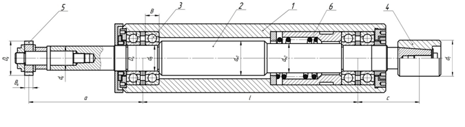
Figure 5 – The circuit design of electrically operated spindle node wheelhead machine model 3А227П: 1 – housing electrically operated spindle node, 2 – spindle shaft, 3 – bearings, 4 – driven pulley, 5 – arbor with a grinding wheel, 6 – spacer
Consider the spindle shown in figure 5, as the beam on elastic bearings with an astringent damping, and will be calculated scheme (Fig. 6).
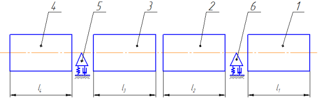
Figure 6 – The calculation scheme of electrically operated spindle node: 1 – slave pulley; 2, 3 – areas of electrically operated spindle unit; 4 – start of a spindle; 5,6 – support of the bearing
The calculation of dynamic characteristics of electrically operated spindle node is carried out with the help of the program on the PC in the package Mathcad. As initial data for calculation are: running mass and moments of inertia sites electrically operated spindle node, stiffness and damping value in the pillars.
The result of the calculation are graphs of the amplitude-frequency characteristics (AFC) and the amplitude-phase-frequency characteristics (АPFC), as shown in figure 7 and figure 8.
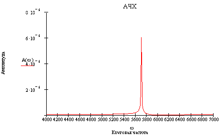
Figure 7 – Graph of the amplitude-frequency characteristics of electrically operated spindle node internal grinding machine mod. 3А227П
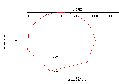
Figure 8 – Graph of the amplitude of phase-frequency characteristics of electrically operated spindle node internal grinding machine mod. 3А227П
On schedule frequency response define, that the change of the amplitude occurs when the circular frequency ω = 5700 rad/s, that corresponds to the natural frequency of oscillation electrically operated spindle node f = 907 Hz. Carry out processing in the 30% range of own frequency of fluctuations of electrically operated spindle node, that is, 272 Hz, it is not recommended, as to the occurrence of the phenomenon of resonance oscillations - the system becomes unmanageable. This phenomenon is negative, due to which it is impossible to conduct mechanical processing with the given accuracy.
Consider the range of frequency of rotation, which is processing the intragrinding machine 3А227П. Grinding of holes D=45 mm runs at a speed of grinding wheel Vк = 20 m/min.
The number of revolutions of the motor nm=2880 rev/min(ωm=302 rad/s), that corresponds to the frequency of forced vibrations of fm=48 Hz; spindle grinding wheel rotation frequency nw = 9555 rev/min (ωw=1000 rad/s), that corresponds to the frequency of forced vibrations of fw=160 Hz.As you can see, forced oscillation frequency electrically operated spindle node does not coincide with the frequency of oscillation, and do not fall in the 30% range, and, consequently, the resonant phenomena did not occur.
Conclusions
In the given work the analysis of existing methods of optimization of modes of grinding and it is established, that the use of the General indicators of the regimes of the grinding process, обеспечиващие stable parameters of quality, can help reduce the intensity of the search for optimal regimes.
On the basis of the analysis of the existing design of the device for grinding the elastic pattern is planned to propose the construction of a grinding head, which can be applied with internal grinding on an elastic circuit with a constant pressing against the PKK to the sample surface, providing the possibility of internal grinding of holes, the radius of which exceeds the course of the front pasterns, execution of grinding the outside cylindrical surface, preserving the quality of processing and material costs.
There are also a calculation of dynamic characteristics of electrically operated spindle node the method of initial parameters in the matrix form, which allows to determine the bottom of own frequency of oscillation of the electrically operated spindle node, in which can cause the phenomenon of resonance.
Important note
When writing this abstract master's work is not yet completed. Final completion: December 2012. The full text of work and materials on the topic can be obtained from the author or his head after the specified date.
List of references
- Резников А.Н. Абразивная и алмазная обработка материалов. Справочник / Под ред. А.Н. Резникова. – М.: Машиностроение, 1977. – 391 с.
- Матюха П.Г. Научные основы стабилизации выходных показателей алмазного шлифования с помощью управляющих воздействий на рабочую поверхность круга: Автореф. дис.... докт. техн. наук: 05.03.01 / Матюха Пётр Григорьевич, Харьк. госуд. политехн. ун-т. – Харьков, 1996. – 48 с.
- Полтавец В.В. Обоснование режимов шлифования труднообрабатываемых материалов при электроэрозионном воздействии на рабочую поверхность круга: Автореф. дис…. канд. техн. наук: 05.03.01 / Полтавец Валерий Васильевич, Донецк. национальн. техн. ун-т. – Донецк, 2001. – 19 с.
- Матюха П.Г. Определение режимов плоского шлифования твердых сплавов с использованием нового критерия о текущей лимитированной режущей способности круга/ П.Г. Матюха, В.Б. Стрелков, В.В. Полтавец // Сверхтвердые материалы. Научно-теоретич. журнал. – Киев: 2004. – № 3. – С. 67-73.
- Матюха П.Г. Определение оптимальных режимов при алмазном шлифовании твердых сплавов по упругой схеме с периодическими электроэрозионными воздействиями на рабочую поверхность круга / П.Г. Матюха, В.Б. Стрелков // Сучасні технології в машинобудуванні. Зб. Наукових статей/ Уклад. А.І. Грабченко: За заг. ред. А.І. Грабченка. – Харків: НТУ „ХПІ”, 2007. – С. 330-332.
- Матюха П.Г. Узагальнені режими процесу шліфування, які забезпечують стабільні показники якості / П.Г. Матюха, В.В. Полтавець // Наукові праці Донецького національного технічного університету. Серія: «Машинобудування і машинознавство». Випуск 7 (166). – Донецьк: ДВНЗ «ДонНТУ», 2010. – С.35-49.
- Матюха П.Г. Определение оптимальных режимов шлифования с электроэрозионными управляющими воздействиями на рабочую поверхность круга/ Физические и компьютерные технологии в народном хозяйстве. / П.Г. Матюха, В.В. Полтавец // Труды 8-й международной научн.-техн. конф. 9-10 декабря 2003 г. – Харьков: ХНПК “ФЭД”, 2003. – С. 151-155.
- Матюха П. Режущая способность рабочей поверхности круга как ограничивающий параметр производительности шлифования / Петр Матюха, Валерий Полтавець // Надежность инструмента и оптимизация технологических систем. Сб. научных трудов. – 2003. – вып. 13, – с. 159-164.
- Корчак С.Н. Производительность процесса шлифования стальных деталей / Корчак С.Н. – М.: Машиностроение, 1974. – 280с.
- Патент України №91235 С2 МПК В24В47/00 Пристрій для круглого шліфування / Матюха П.Г., Полтавець В.В., Жулін І.С., Габітов В.В. Заявка а200803398 від 17.03.2008. Опубл. 12.07.2010 бюл. №13, 2010 р.
- Патент України №94813 С2 МПК В24В41/00 Шліфувальна бабка / Матюха П.Г., Габітов В.В., Войтов М.С., Благодарний А.О. Заявка а200911849 от 19.11.2009. Опубл. 10.06.2011 бюл. №11, 2011 р.
- Заявка а201012927 Україна, МПК В24В41/00. Навантажувальний пристрій для шліфування / Матюха П.Г., Габітов В.В., Благодарний А.О. заяв. 01.11.2010.
- Машиностроение. Энциклопедия в 40 томах. Том 4-7. Металлорежущие станки и деревообрабатывающее оборудование. М.: - Машиностроение. 2002. – 864 с.
- Орликов М.Л. Динамика станков / М.Л. Орликов – 2-е изд.,перераб. и доп.- К.: Выща шк.. Головное издательство,1989, - 272с.