Abstract
Content
- 1. Urgency
- 2. Problems
- 3. Air supply control divice
- 4. Development of automated control system for vibration-pneumatic separator
- References
Urgency
The current difficult situation in the energy sector increases the role and importance of Ukrainian coal as a guarantor of the state's energy independence [1]. Coal is one of the main primary energy resources of Ukraine [2].
To turn coal into energy with high efficiency preparation the coal has to be done at the first place. For coal preparation at the mineral processing plants special equipment and variety of methods are used. At this stage preparation of the coal is almost not automated, which negatively affects the efficiency of the relevant processes.
The most important technological parameters of vibration-pneumatic separator are as follows: air flow, feeder loading, frequency of air flow pulsations, and amplitude of shaking of the box. The advantages of vibration-pneumatic preparation: simple preparationТs scheme, lower capital costs and the cost of the process, no water consumption.
The purpose of this work is to increase the productivity of the vibration-pneumatic separator by creating a system for automatic control of its technological parameters.
Problems
1. Analysis of vibration-pneumatic coal preparation technology.
2. Development of mathematical model with the purpose of examining the motion of separatorТs bed particles. Analysis of received simulation results.
3. Separator control algorithm development
4. Synthesis of vibration-pneumatic separator control system.
5. Development of the means for the system creation.
Air supply control device
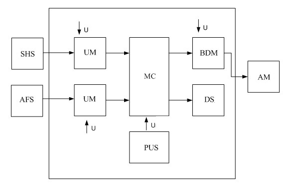
To increase the vibration-pneumatic coal preparation efficiency the air supply control device has been developed. Figure 1 shows the block diagram of the air supply control device.

Figure 1 Ц The block diagram of the air supply control device
From the stratum height sensor (SHS) and from the air flow sensor (AFS) through a unit matching signals are passed to the microcontroller (MC). Microcontroller compares the actual height of the stratum received from stratum height sensor with a given height signal and if the signals are different, microcontroller generates the control action to increase or decrease the air flow rate. The signal from the microcontroller through the block devices matching (BMD) affects thе actuating mechanism which is represented by DC motor. The DC motor rotates the valve in the pipe (through which the air flows under the deck of the separator) until the actual height of the stratum becomes equal to the given height.
Air supply control device allows us to control the technological parameters and provides with the necessary supply of air in the pipes of the separator.
Development of automated control system for vibration-pneumatic separator
The main machine of a plant (vibration-pneumatic separator) is subjected to a considerable idle time. The reason is absence of executive mechanisms for regulation of technological parameters. Also there is no sensor for measuring bed's loosening and no control system for the preparation process which leads to considerable influence of the human factor on efficiency of separation [3].
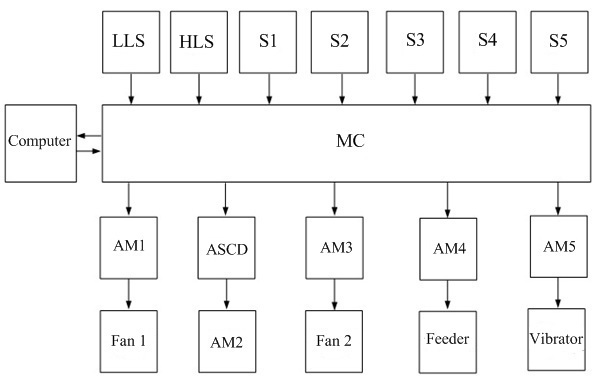
Figure 2 shows the block diagram of the control system of vibration-pneumatic separator.

Figure 2 Ц The block diagram of the control system of vibration-pneumatic separator
Abbreviations on Figure 3: LLS Ц low-level sensor; HLS Ц hight-level sensor; S1 Ц frequency rotation sensor of the drive fan shaft; S2 Ц sensor layer height; S3 Ц rotation frequency sensor of the technology drive fan shaft; S5 Ц vibratorТs drive shaft speed sensor ; AM1 Ц AM5 Ц actuating mechanism. ASCD Ц air supply control device. Firstly checking the level of material in the hopper needs to be executed. Then the fan of dust collecting system is turned on (to ensure removal of the air laden with dust). On reaching the rock mass the upper level the sensor will respond.
Figure 3 shows the algoritm of automated control system for vibration-pneumatic separator.

Figure 3 Ц The algoritm of automated control system for vibration-pneumatic separator
(animation: 12 frames, 5 cycles of repeating, 28 kilobytes)
References
- ”гольна€ промышленность ”краины: факты, цифры, перспективы. [Ёлектронный ресурс]. Ц –ежим доступа: ukrrudprom.ua
- ”гольна€ промышленность ”краины (2007 г.). [Ёлектронный ресурс]. Ц –ежим доступа: ukrexport.gov.ua
- Ћогинов ¬.ј., √авриленко Ѕ.¬. —истема управлени€ вибропневматическим сепаратором. [Ёлектронный ресурс]. Ц –ежим доступа: masters.donntu.ru
