
Abstract
Content
- Introduction
- 1. Analysis of mathematical model concepts and methods of modeling of digital devices
- 1.1 The models of digital devices
- 1.1.1 The Functional Model
- 1.1.2 The structural model
- 1.2 Logical modeling of faulty digital devices
- 2. Statement of the problem of construction tests
- 3. Methods of construction checking tests
- 3.1 The main provisions of the construction of tests
- 3.2 Structural test methods of construction are not targeted at specific problem
- 3.3 Structural methods for constructing tests for a given fault
- 3.4 The role of observing strategy to build off of reactions with the memory test the CO
- Conclusion
- References
Introduction
The wide spread of computer technology and digital technology in all areas of modern society increases the demands for quality and reliability of the devices used. Improved components and architecture, increased integration and reliability of digital devices (CC) are not possible without effective computer-aided design and diagnosis of digital systems. An important role in automated diagnostic systems are subsystems of diagnostic testing and modeling. The effectiveness of such systems based on the test object is applied to a specially organized (test) influences to a large extent depends on the methods and algorithms for constructing checking tests and simulations. The use of such systems can improve the quality and reliability, reduce design time and diagnostic control goal.
Research problems of diagnosis and fault-tolerant design of digital devices dedicated to the ongoing regular international symposia, conferences and school seminars: IEEE VLSI Test Symposium (IEEE VTS), IEEE Euro Test Symposium (IEEE ETS), International Conference "Design, Automation & Test in Europe" ( DATE), IEEE East-West Design & Test Symposium (IEEE EWDTS, a symposium led by the Kharkiv National University of Radio Electronics), IEEE Latin American Test Workshop, etc. There is an international council on technology testing - Test Technology Technical Council (IEEE TTTC), brings together scientists and engineers working in the field of reliability problems and test the CO, and sponsored by the international scientific and technological society, IEEE Computer Society. All this is eloquent testimony to the extraordinary relevance of the research issues of reliability and diagnosis of digital circuits.
There are currently a number of effective methods for generating tests for verifying digital circuits. A significant contribution to the development of testing digital systems have foreign researchers Roth JP, Zorian Y., Agrawal VD, Abramovici M., Fujivara H., Ivanov A., Prinetto P., Pomeranz I., Reddy SM, Rudnick EM, Patel JH and our scientists Parkhomenko, PP, Loaf MF, RR Ubar, Totsenko VG, Speransky DV, Tverdokhlebov VA Romankevich AM, Derbunovich L. , Krivulya GF, Skobtsov JA, Hahanov VI, Kharchenko VS, Zinchenko, YE and others. However, existing methods do not always allow us to construct tests of high completeness within a reasonable time. This primarily relates to digital circuits with memory.
Thus, the construction of tests for verifying digital circuits with memory is an important scientific and technical problem, the solution of which significantly affects the quality and reliability of digital systems. This paper will be reviewed and investigated the structural, analytical and evolutionary approach to the generation of test checking of digital circuits with memory.
1. Analysis of mathematical model concepts and methods of modeling of digital devices
1.1 The models of digital devices
In the process of design automation and diagnosis of digital systems (CAs) are widely used verification systems, modeling and generation of validation tests, which use appropriate mathematical model. The object of this study are digital devices (CO), under which, generally refers to devices that process binary (digital) information. They in turn are divided into two classes [1-3]: combinational circuits - devices without memory (without feedback) and sequential circuits - devices with memory (with feedback). In constructing models of the CO is used as a functional and structural approach.
1.1.1 The Functional Model
The essence of the functional approach is an abstraction of the internal organization of the device, and considering only its logic function.
Models of combinational circuits. As a functional model of combination devices often use a system of Boolean functions:
z1 = f1(x1, ..., xn)
...
zm = fm(x1, ..., xn),
where X = (x1, ..., xn) – входные, Z = (z1, ..., zn) – output variables with binary values B2 = {0,1}.
The system of Boolean functions describe the Raman CC, which has n inputs, m outputs, and is shown in Fig. 1.1.
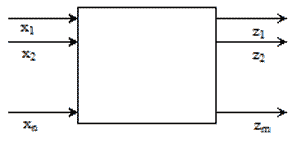
Figure 1.1 – Raman FD
Here, every Boolean function fi(x1, ..., xn) - this map B2n —> B 2. The simplest way to represent a Boolean function is a truth table.
1.1.2 The structural model
Information about the logic of the functioning of the CO, which is given by the above functional model is inadequate to address the construction of tests and simulations. In the development of algorithms for constructing tests and simulation is increasingly used the structural model of digital device, reflecting, except for the logic operation of the CO, the relationship between its components and the environment. As a structural model of the CO, as a rule, used the correct logical network or logic. The logical network or scheme - it is a directed graph whose vertices are the elements of logic, inputs, outputs, and the branching nodes. Directed arcs of the graph show the network connection. The correct logical network - a network whose outputs are no two elements are not connected together and each of the functions implemented on the outputs of the CO, can be represented as a Boolean function output devices or combination of a finite automaton in the case of the CO with the memory. The basis of the network are the logical elements of two types: 1) the elements whose operation is described by Boolean functions, and 2) memory elements, the operation is described by a model of a finite automaton.
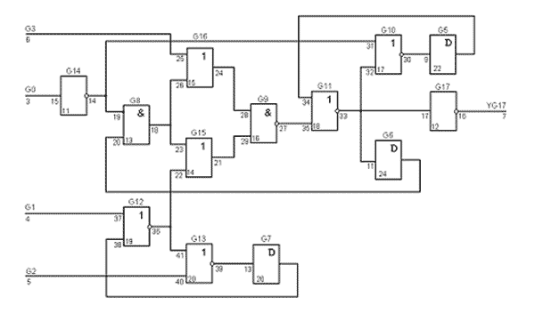
Figure 1.2 – Represented by combinational logic from the catalog s27 ISCAS-89
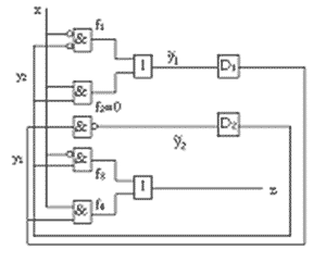
Figure 1.3 – An example of sequential circuits
1.2 Logical modeling of faulty digital devices
Modeling of the CO with defects is one of the most important parts of logic simulation is used in computer-aided design (CAD) and diagnosis of computer systems in solving these problems [2]:
- Determine the effectiveness of the test sequence - its completeness and diagnostic features;
- Construction of dictionaries for diagnostic troubleshooting of logic circuits;
- Generation of validation tests (as a tool to determine the effectiveness of the generated sets);
- Analysis of the behavior of the scheme and its properties to a malfunction.
To meet these challenges, the program simulation of faulty circuits, the following information:
- Description of the logic circuit;
- Description of test input sequence;
- Model and a list of processed faults.
The functional structure of the system simulation of faulty digital circuits is shown in fig. 1.4.
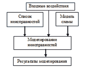
Figure 1.4 – Simulation of faults
2. Statement of the problem of construction tests
The essence of the problem of constructing a test is to find a binary input sequence, which, for each fault in a given set gives a different output signal values in the intact and defective circuits. As a rule, are considered single stuck-fault. We believe that the single constant fault (single stack-at fault) acts only on the connection between the valves [1-3]. Each line of the circuit can have two types of faults: the constant 0 and the constant 1 (sa-0, sa-1). Thus, constant fault records on the line signal is a constant value of 0 or 1 (sa-0, sa-1), regardless of the value applied to its signal.
Under the test to understand the sequence of input actions, output analysis of reactions that can either check the serviceability of the test device, or to determine the location of faults contained in the device [1, 2].
We say that a test be complete if it checks all the fault of a given class. The best part may not be used during regular operation. Next, we consider only test diagnostics
3. Methods of construction checking tests
3.1 The main provisions of the construction of tests
The purpose of automated test generation is to construct a test forthe scheme. Thus, ideally, it is desirable that [2]:
1) the completeness of checking test was maximal; 2) the generation of tests was minimal; 3) The test was built by the minimum length.
These conditions result from economic and technological requirements. Obviously, the completeness of the test directly affects the quality of the product. The length of the test affects thecost of testing the CO determines the characteristics required of testers (in particular, the amount of memory) and time of testing.
It should be noted that the completeness of the test must bechecked to determine the relative (non-redundant) faults. For example, for the scheme, which has 5% of excess malfunction of, obviously test the completeness of 96% is clearly unattainable.Because sometimes distinguish between completeness and efficiency of the test, which are defined as follows [2].
Completeness – P = O / N, where N - total number of faults and O – the number of checked in this test failures.
Efficiency – P = O / (N – R), where R – the number of redundant faults.
Quantitative values of the completeness and effectiveness of the testalso depends on how many faults formed. Modern systems generally use methods of reducing the list of faults, based on relations of equivalence and dominance [2].
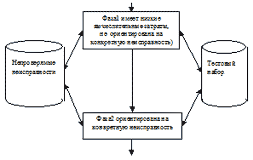
Figure 3.1 – The structure of the test generation
3.2 Structural test methods of construction are not targeted at specific problem
At the initial stage of the generation of inspection tests (I phase) are used to quickly acting and easy to implement methods which allowrye with a small amount of time to get a test for painnecks of the fault. One such method is a pseudorandom test generation method, described in detail in the literature [1–3]. This method is not focused on a specific problem and is building a test for the whole circuit. It is relatively simple to implement, has high speed and for some classes of circuits provides a fully satisfactory tests (especially for combinational circuits). This is due to the wide application of this method in a computer-aided construction of tests [20, 21]. The most important component of this method is faulty circuits simulation program that allows you to select the test the impact of the randomly generated set of binary vectors. When implementing this method uses software generators of pseudorandom binary numbers. In the simplest case of a binary pseudo-random set is processed as follows. For the current random binary vector Xi with the help of a simulation with a fault is determined by the value of n (Xi), which characterizes the number of faults to be checked on a set of Xi, excluding those faults that are tested previously constructed test sequence X1, X2, ..., Xi-an.Further, if n (Xi) >= T (threshold), the set Xi is included in the test sequence and generates the following pseudo-random set. If n (Xi) < T, then the input set is rejected and not included in the test. A simplified block diagram of a pseudo-random test generation algorithm is presented in Fig. 3.2 [2].
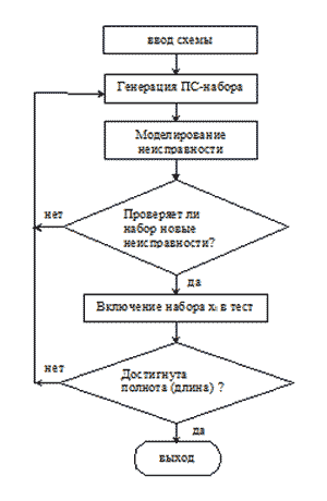
Figure 3.2 – Pseudo test generation
3.3 Structural methods for constructing tests for a given fault
At present, there are many structural methods, which are used for solving test generation for a given problem. They have in common is that they are more or less based on the activation of ways to help valued alphabets. The first regular method, for which the theoretically proven that it ensures the construction of tests for nonredundant faults in the combinational circuit is a D-algorithm [24]. This method and its subsequent modifications were very common in the 70s. }, where {0,1} denote the usual (Boolean) values, {D, D'}. The basic D-algorithm was used to activate a multi-dimensional and 6-digit alphabet T6 = {0,1, D, D ', u, ∅} means conflict (contradiction) in the process of test generation. ∅ mismatch signals in intact and faulty circuits, u - undefined and However, despite the popularity of this method, its operation has shown that there exists a class of schemes that contain a large number of converging branches, which in the process of generating the test sequence there are too many conflicts. For such schemes has been proposed a method PODEM [25,26], which also used the 6-digit alphabet, but used very different strategies for searching and processing of conflicts in the process of test generation. This method proved to be much easier to program implementation than the D-algorithm, and more efficient for large combinational circuits up to several tens of thousands of gates [27]. The ideas embodied in the successful development of PODEM got in [28], which developed a method of FAN (fan-out-oriented test generation algorithm). In this method, at the stage of preprocessing is carried out additional analysis of the scheme, in which the CO is divided into tree-like subcircuits, which allowed the development of more effective procedures to promote
The mutation operator (SM) at random (with small probability) to alter any gene (control) strings. Using these three basic operators, the population (the set of potential solutions to this problem) evolves from generation to generation. Block diagram of the classical genetic algorithm is shown in Figure 3.4.
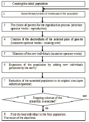
Figure 3.4 – The classical genetic algorithm
3.4 The role of observing strategy to build off of reactions with the memory test the CO
Formulation of the problem of building inspection tests and modeling faults for the CO to the memory depends on the applied strategy of monitoring the output signals [2, 58, 59]. As a general rule, most used in practice of structural methods to allow for sequential circuits, not all output signals and implicitly assume a set of chains of memory elements. A more complete use of the output signals for all times and all outputs can significantly improve the completeness of the test for circuits with memory [2, 58, 59].
There are two strategies for monitoring reactions of the CO output of memory: a single observation strategy used in most structural methods for constructing tests for the CO-memory, and multiple surveillance strategy, based on the principles of the theory of finite automata experiments [2, 58, 59]. The principal difference between these strategies is the following. According to the strategy of a single fault is detectable and, therefore, it is possible to construct a test sequence) if there exists a time t, so that regardless of the initial state of a functioning and malfunctioning circuits output values are different for intact and faulty circuits. That is, all pairs of states intact, and the faulty circuit give different output signals in the same time. According to multiple strategies for each pair of states intact, and the faulty circuit has its own time, in which they give different outputs. That is, different pairs of states serviceable and failed the CO may vary at different times. This seemingly small difference leads to the fault, which is the subject of netestiruemoy first traditional strategy, in fact, has a checking test in the case of a multiple strategy.
Conclusion
Thus, the current advanced research in the field of test construction are to investigate the possibility of using multiple strategies, and monitoring developments of the theory of experiments with finite automata in the process of constructing and evaluating the effectiveness of tests for the CO with the memory at the structural level. In this case it is important to study possible methods of implementing this approach:
- The use of symbolic simulation;
- The use of multi-valued logics;
- The application of evolutionary algorithms, in particular, GA.
In this regard, to increase the efficiency of the automated generation of tests for checking the CO with the memory necessary to solve the following tasks:
- Investigation of the effect of different strategies to monitor the output signals on the efficiency of test generation for sequential digital circuits.
- Research and development of structural and structural-analytical methods for constructing test sequences for verifying circuits with memory-based strategy for monitoring multiple outputs.
- Research methods and multi-valued logic simulation smivolnogo to improve the efficiency of test generation for sequential circuits based on multiple strategies of observation output.
- Development of a method of generation of tests for checking the memory circuits using genetic algorithms and characteristic sequences.
Development of appropriate software validation test generation for the CO with the memory.
References
- Барашко А.С., Скобцов Ю.А., Сперанский Д.В. Моделирование и тестирование дискретных устройств. – Киев: Наукова думка, 1992. – 288с.
- Ю.А.Скобцов, В.Ю.Скобцов. Логическое моделирование и тестирование цифровых устройств. – Донецк: ИПММ НАНУ, ДонНТУ, 2005. – 436 с.
- Abramovici M. Digital System Testing and Testable Design. – New York: Computer Science Press, 1990. – 652 p.
- Thompson E.W., Szygenda S.A. Digital logic simulation in a timed-based, table-driven environment. Part 2. Parallel Fault Simulation // Computer, IEEE Comp. Society. – 1975. – N 3. – P.38-49.
- Levendell Y.H., Menon P.R. Comparison of fault simulation methods – treatment of unknown values // Journal digital system. – 1980. – N 4. – P.443-459.
- Armstrong D.A Deductive method for simulating faults in logic circuits//IEEE Transactions on Computers.-1972.-N 5.-P.38-49.
- Биргер А.Г. Многозначное дедуктивное моделирование цифровых устройств // Автоматика и вычислительная техника. – 1982. – №4. – С.77-82.
- Ulrich T.G., Baker T. Concurrent simulation of nearly identical digital networks//Computers.-1974.-N4.-P.39-44.
- Yu.A.Skobtsov, V.Yu.Skobtsov, D.E.Ivanov Evolutionary distributed test generation methods for digital circuits // Proc. of 8th International Workshop on Boolean Problems, Freiberg, Germany, September 2008. – P.213-218.
- T. Marcas, M. Royals and N. Kanopoulos, “On distributed fault simulation”, IEEE Computer, vol. 7, Jan. 1990.- P. 40-52.
- S. Patil, P. Banerjee and J. Patel, “Parallel test generation for sequential circuits on general purpose multiprocessors”, in Proceedings of the 28th ACM/IEEE Design Automation Conference, (San Francisco, CA), June 1991.
- S. Ghost, “NODIFS: a novel, distributed circuit partitioning based algorithm for fault simulation of combinational an sequential digital design on loosely coupled parallel processors”, tech. rep., LEMS, Division of Engineering, Brown University, Providence, RI, 1991.
- Corno F., Prinetto P., Rebauden M., Sonza Reorda M., Veiluva E. A PVM tool for automatic test generation on parallel and distributed systems // Proc. Int. Conf. on high-performance computing and networking. – Milan, 1995. – P.39-44.
- Muth P. A nine-valued circuit model for test generation // IEEE Trans.Comput. – 1976. – N6. – P.630-636.
- Cha C.W., Donath W.E., Ozguner F. 9-v algorithm for test pattern generation of combinational digital circuits // IEEE Transactions on Computers. - 1978. - №3 - P.193-200.
- Sziray J. Test calculation for logic networks by composite justification // Digital Process. – 1979. – № 5. - P.3–15.
- Cheng W.T. Split circuit model for test generation // 25th Design automation conference proceedings. – 1988. - P.96–101.
- R.Krieger, B.Becker, M.Keim. Symbolic fault simulation for sequential circuits and the multiple observation strategy// Proc. design automation conf.– 1995.– P.339–344.
- B.Becker,M.Keim. Hybrid fault simulation for synchronous sequential circuits//Journal of electronics:Theory and applications.-1999.-15.-P.219-238.
- M.Keim, N.Drechsler, R.. Drechsler, B.Becker. Combining Gas and symbolic methods for high quality tests of sequential circuits// Journal of electronics:Theory and applications.– 2001. – 17. – P. 37-51.
- Скобцов В.Ю. Символьное моделирование неисправностей последовательностных цифровых устройств // Автоматика и вычислительная техника. - 1997. - №5. - С.40-50.
- Скобцов В.Ю., Скобцов Ю.А. Генерация проверяющих тестов для последовательностных цифровых устройств на основе символьного моделирования // Автоматика и вычислительная техника. – 1999. – №4. – С.73–84.