
Computer systems and networks
Digital signal processing (DSP) gives truly limitless abilities in the spheres of various signals processing. It appeared in 1960-1970’s in the times of the first digital computers. However, high computer prices constrained DSP to the few critical tasks and vital spheres. Among the first attempts of the DSP application, together with radiolocation, hydro location (important issues of the government security), oil deposits search, (this sphere promised high returns), outer space studies, radiography also was present (as the sphere that was saving human lives).
Having succeed in radiography and after revolution in the computer sphere in 1980-1990’s, DSP started its further successful application in the medicine. Nowadays DSP has successfully made a revolution in such areas as:
It can also be noticed that the definition of signal processing
was first met exactly in the medicine,
seeing cardiograms mathematical analysis, which was started by Einthoven in 1903 [2].
Later in 1906, he applied telemedicine technology for the first time – transmitted ECG to some distance.
Willem Einthoven was awarded Nobel Prize For the electrocardiogram mechanism discovery
in 1924.
Nowadays in connection with the electronics and microprocessor technology development, there appear portable medical diagnostic appliances that can be successfully used in everyday life. One of the modern medicine major problems is identification at different stages and prevention of the heart disease.
Electrocardiography (ECG) is one of the leading methods of instrumental research of the cardiovascular system, which remains the most widespread and accessible method to a wide range of people. For continuous monitoring of the cardiovascular system and in order to obtain timely assistance, remote patient monitoring method by the attending physician is possible to apply.
The availability of regular heart monitoring will allow identifying such diseases on the early stage of the heart disease, to facilitate the timely appointment of the medicines and reduce treatment costs. Digital signal processing may significantly reduce the necessary equipment costs as well as to increase registration equipment reliability and accuracy. This direction of transfer of the electrocardiogram signal processing from analog part to digital one is especially important. This is relevant to the increase in the number of heart disease.
While working on this topic different ways of filtering electro-cardio signal are going to be studied and the optimal algorithm for implementation in portable devices are to be developed. The list of tasks to be addressed:
To achieve these goals the plan, which will be the result of the Master's work, has been developed. The plan includes the following items:
The practical significance of this work will be in a noisy signal processing algorithms that may be implemented in portable devices as well as analyzing the requirements for them.
As everybody knows, electrocardiogram is a recording and investigation technique of the electric fields produced by the work of the heart [3].
The ECG signals can be overlapped by the various kinds of noise and interference. The main sources of noise and interference are:
The standard clinical ECG operates with a frequency band 0.05 - 100 Hz [4]. This frequency interval will stand out from the initial one and any unwanted frequencies will be eliminated from it.
There are two main methods for removing unwanted frequencies from the signal. Firstly, FFT can be performed above the input samples. In the resulting frequencies array reset undesired frequencies, which are the result of interference. Resetting of the given coefficients will be quite trivial task. The main problem becomes FFT itself because of very cumbersome implementation in a portable device.
Another possible option is digital filters usage. They represent a linear discrete system that convert the input sequence to the output with the algorithm described by the difference equation. They make it possible to recover a signal that was somehow distorted. The solution of this task can be accomplished using analog filters, but digital filters are able to achieve much higher accuracy.
There exist four main types of digital filters: low pass (a), band (b), high (c), notch (d) Fig. 1.

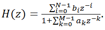
The easiest way to implement the digital filter is the convolution of the input signal with the impulse response. Using this method, almost any linear filter can be built. Filters based on the convolution operation are called “not recursive”. Each sample of the output signal is obtained by multiplying the input samples by the appropriate weighting coefficients and the subsequent summation of the results. Not recursive filters based on convolution are called filters with the finite impulse response (FIR filters). They are described by the following transfer function [5]:
 (1)
(1)
Other forms of digital filters construction are recursive filters.This class is broader. In addition to the input signal sampling, samples of the output signal, obtained from previous iterations, are also taken into account. Recursive filters are called filters with infinite impulse response (IIR - filters). The transfer function in general form is as follows:
 (2)
(2)
It corresponds to reaction computing algorithm in the form of equations difference:
 (3)
(3)
In addition to the general form (2) the IIR transfer function can be represented in other equivalent forms [6], among which the following two are of our interest:
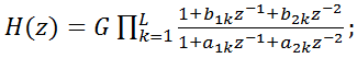 (4)
(4)
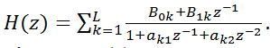 (5)
(5)
FIR filters transfer function (1) corresponds to the difference equation:
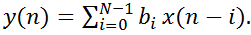 (6)
(6)
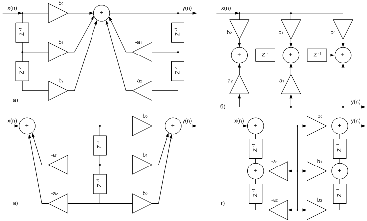
Thus, the digital filter structure, that shows the reaction calculation algorithm, is determined by the type of transfer function. Main types of IIR filter transfer functions:
They are respectively determine three main structures of the IIR filters (Fig. 2):
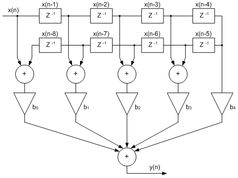
The transfer function (1) defines the direct FIR filter structure. It appears mainly in two varieties:
The structure of the FIR filter with symmetric impulse response is shown in the Fig. 3.
Digital filters can be classified according to their applications and structure in the table 1. By their applications filters are divided into three major groups: time processing filters, frequency processing filters and special filters. Since the information in the input signal will be presented in time domain, this group of filters is of greatest interest. According to digital filters internal structure they are divided into the above-mentioned FIR and IIR.
Table 1 - Clasification of filters
| By application |
|
|
| On the convolution basis (FIR) | With a recursive structure (IIR) | |
| Time processing filters | Homogeneous filters | Single-pole recursive filters |
| Frequency processing filters | Window filters | Chebyshev filters |
| Special filters | Special FIR filters | Filters with iterative structure |
As shown in Table 1, FIR and IIR filters amount to two class of filters. The issue of choice on which of the classes the algorithms are to be implemented will be resolved in my Masters work.
At this stage, the electrocardiogram device scheme was developed for further processing in the MATLAB.
The scheme is presented in the Fig. 4.

Below (Fig. 5) the initial and filtered signals by band pass filtering and sequential cut filter as well can be seen
In writing this abstract master's work is not yet complete. Final completion: December 2012. Full text of the work and materials on the subject may be obtained from the author or his scientific adviser after that date.
Компоненты и технологии- 2008 - ноябрь - 146 с.
Компоненты и технологии- 2009 - январь - 108 с.