About submersible hydropercussion plants you can find information on the site DonNTU Masters (Masters of the Department of Technology and technology exploration), whose work often dealt with themes of well drilling on the continental shelf .
Structural and multifunctional hydropercussion drill (GBS) comprises three main elements: hydropercussion mechanism to transfer the dynamic loads on the bottom hole, auger kit (CL) for the formation and coring wells at a given interval, and the starting node (upper - and lower WTP - BMPs), principally designed for the termination or communication with the flow of working fluid chambers hydropercussion mechanism and the core set.
The scheme developed hydropercussion drill is shown in img. 5. The proposed GBS saved the composition and structure of executive communications elements characteristic of shells used in the well-known devices such as UMB and UGVP. However, in the construction of hydraulic hammer and starting node changes significantly improve the operational performance GBS.
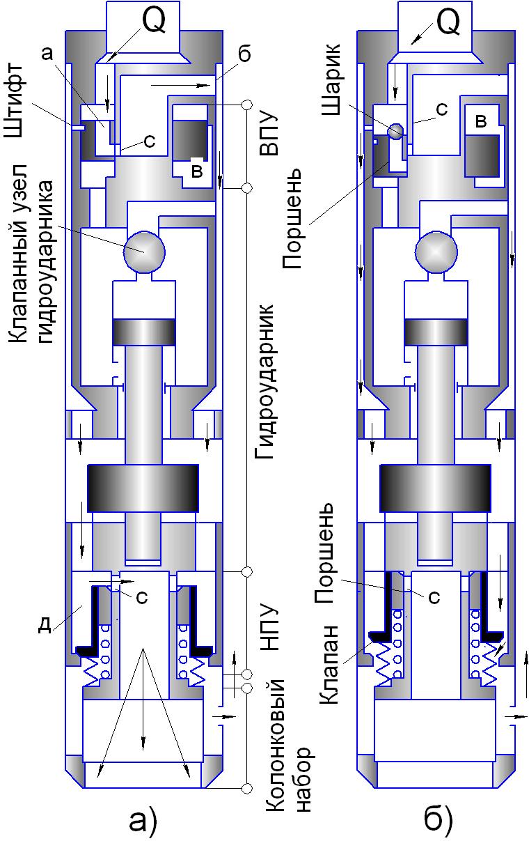 Image 5 – Schematic diagram of the drill hydropercussion
The fundamental difference of hydraulic hammer is designed remote version of impact site and hydraulic performance of the shock mehanizma.Odnokorpusnoe site has reduced the number of intermediate links in the "striker, anvil - CN." Exclusion from the system of additional threaded connection on the interval "peen-anvil" can be considered as a solution that provides increased power transfer coefficient of a shock to the bottom hole. According to the data in a threaded connection to the movement of the shock pulse, which is formed in the collision of the hammer and the anvil of the impact energy losses reach 15 - 30%.
Hydraulic isolation of the chamber allowed the striker to ensure a guaranteed starting hydraulic hammer while running it into the sanded-in the well. The camera striker, even penetrating into the sand, scale or sludge is cleaned-off incident constant stream of fluid. There was also an opportunity to apply to the construction more massive hydraulic hammer strikers, with the same length as in the operation of facilities does not violate the requirements for the removal of the projectile size overboard.
The principal changes made to the structure and nature of the starting node, subject to the fulfillment of identity as the CPG, and NEC. Using a two-element nodes in the launch locking device, based on a spring, to be sure that the blocking phase of the hydraulic hammer on the erosion of rocks with a reliable locking system return to its original position with the restoration of ties with the working chambers of the hydraulic fluid flow, and isolation chamber core lifter from the flow of liquid waste at the start and hydraulic hammer work. The proposed scheme provides the ability to launch sites quickly and repeatedly change the destruction of the rain on the range of drilling, which is an effective alternative to sinking intervals dense argillaceous rocks or sands, due to the ability to use shock-wash boring these rocks, instead of traditionally used labor-intensive "pecking" method.
During the implementation of Interval drilling in the cycle of alternation means of destruction of precipitation are two states GBS:
work - on a set of core phase of the diving into the ground to form the core of kolinsky set (img. 5b);
semi-detached - on stage at the erosion of sediments previously traveled or a specified part of the borehole (img. 5a).
A schematic drawing of the generated hydraulic hammer is shown in (img. 6). Functionally, hydropercussion shell can be used for odnoreysovoy sinking, so when mnogoreysovom drilling. The fundamental difference with respect to the development of well-known shells PBS-127 and PBS-108 is included in the distribution of the hydraulic hammer adapter 1 (img. 6), as well as the remote version of shock and hydraulic PBS site with guaranteed protection of his valve-piston group on the descent zapesochivaniya machine into the well. Single-node performance of the shock on the one hand possible to reduce the length of the firing pin 4 without reducing its weight, which significantly reduced the size requirement for the removal of the installation overboard. On the other hand, the implementation of the scheme combined with the destruction of rain mnogoreysovom drilling became possible operational sequence of rocks jetting failure and shock immersion core projectile at a given interval of the well with only one top node distribution, mode of operation is ensured by the change in the supply of sea water discharge line. Delisting of PBS elements of the lower starting node greatly simplifies not only the design, but a shell operation.
Through the unification of valve design and optimization of the ratio of hydraulic and operating parameters, sufficient strength characteristics of the mechanism at a flow rate of 180-200 l / min. In addition, simplified design of the pump unit PBS valve group is placed directly into the bottom of the anvil 5. Inclusion in the PBS-piston valve 6, performs the role of non-return valve and a kind of lubricator, compensatory changes in the volume of fluid in the chamber the hammer, when it moves, not only provided reliable isolation chambers hydropercussion mechanism against ingress of sand and sludge particles in the descent of a projectile into the hole, but also eliminate fluid from the suction chamber firing pin, allowing a reliable reverse circulation flow in the core lifter 7.
Completeness of PBS when working in odnoreysovogo sampling is shown in (img. 6a).
When you turn on the pump discharge pressure of the liquid hose removed. Name channel adapter and load the channel "a" distribution renick a course falls into the working chambers of the hydraulic mechanism hydropercussion 3 mA, providing a reciprocating translational movement of the piston relatively inside 4. The latter, at the end points strikes the anvil 3 and 5, forming a shock to them, convey core set. Exhaust waste liquids in hydraulic hammer is ensured through a check valve 2 and the box "b."
In implementing the scheme a lot of drilling voyage, the essence of which lies in the interval shaft sinking with alternating erosion of rocks on a given interval of idle wells in the hydraulic hammer (without coring) and face deepening due to high-impact diving drill in the sediments (with coring) hydropercussion mechanism of complement no respect to be equipped with starting node (img. 6, b and c).
In the sampling pump flow corresponds to the nominal for hydraulic hammer (180-200 l / min). In this case the spring 9 force compensates the flow pressure at the surface of the valve 8 (img. 6b). The liquid entering the working chamber via hydraulic hammer "d" of the cylinder 10 and the starting node channel "and" distribution adapter provides a duty cycle of hydrodrummer.
To access the destruction of the rain jetting flow rate increases. As a rule, the phase of erosion sediments pump flow set at a level not less than 400 l / min. With this increase in fluid flow, the valve 8 is formed by the pressure exceeding the force of compression spring 9. The valve is moved down to the landing in the seat 11 of the cylinder 10 (img. 6c). The windows of the "e". Further, the liquid through the window, "Well," channel "to" adapter 1 and the distribution channels shifted the top 3 and bottom 5 anvils, overcoming the force of the spring 12, moves the piston-valve 6 and opens the window "in". Water flow through the inner cavity of the core lifter core catcher-7 and the nozzle 14 in the shoe 13 rushes in the bottom hole, allowing erosion of the rock. If necessary, change the mode of destruction of the rain, in the hydraulic fluid flow rate is reduced to a nominal value for the launch and operation of hydraulic hammer. In this situation, the pressure at the valve 8 is reduced, and the valve spring 8 9 returns to the starting position for the sampling phase.
 Рисунок 6 – Scheme submersible drill installation UMB-2M
Complete support includes two modules: a guide unit and the base bottom. Both modules must be separated into several compact knots in the transport position all dismantled equipment (except for the rack rails) and spare parts are placed in a regular box (1,0:0,7:0,8 m).
In the preparation of support to the work performed separate assembly of the guide unit and the base bottom.
Structural elements of the sending node (img. 8b) are the two front two and moving the carriage 3.
Stand is a piece of drill pipe diameters of 50 mm at the lower end of which is welded on the support tube 3 (img. 8b). By the removable part of the post include a stop and bearing bushing 5.
Movable carriage (img. 8a), designed as a welded housing with guide pipes 2 and 3 spring-loaded latches on which is rotatably secured revolving funnel 5.
When assembling the sending node to the two pillars (img. 8b) are placed bearing sleeve 5 and the carriage 3. Then on top of the rack are fixed removable stops 1.
Bottom base includes a rigid bottom box of compact support, and six feet, a length of 0.8 m.
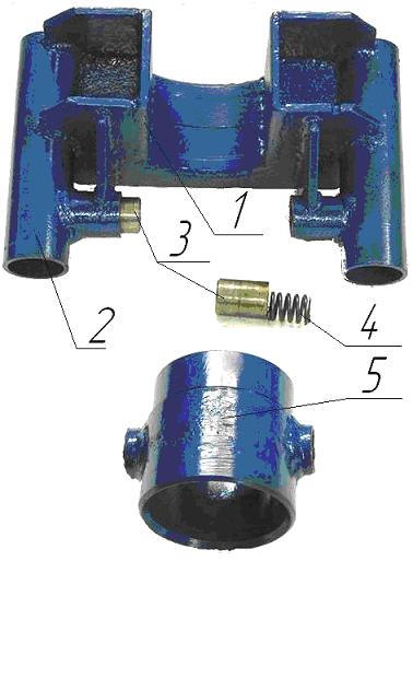

Image 8 – Site Guide: a movable carriage;b-guide complete assembly.
Box body 1 (img. 9a) is mounting with threaded ports for installation sleeve 2 and the guide cylinder 4 convertible poluhomutom 5, which rotates on an axis 7, and in the closed position, the lock is fixed 6. End of the box pants have openings for placement of the support legs.
The support legs are welded frame of segments of drill pipe with a diameter of 50 mm. In front of the lamas in the elongated nozzles installed rubber bumpers. At the opposite end of the frame is made pipe, which is a core element of the mounting feet. Four front legs 3, 5, 7 and 8 (img. 9b) have a connections 10 for the installation of removable support stands 2 and 6.
Assembling the base is placed in the openings of the box pants bearing pads with subsequent fixation of the fingers.
In the future, a smart host supporting pipes placed in the rack mounting boxes and tubes threaded part of the bearing bushing is attracted to the bottom box.
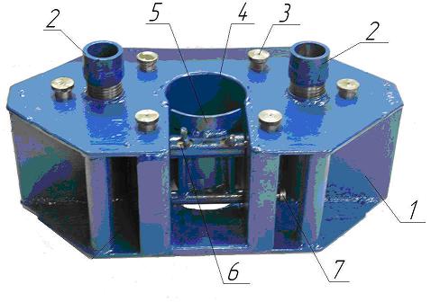

Image 9 – а) Box bottom base, and b) placing the drill in the funnel movable carriage
fluid.
Assembling the installation is completed deployment drill 4 in a carriage turning the funnel (img. 10). At the branch pipes 10 front pads are installed removable support stand 2 and 6, the level surfaces are the same and coincides with the height of the supporting part of the rotary hopper, which allows not only a constant horizon of the projectile with respect to the surface of the deck, but also provides a sheltered location in the drill carriage.
In the vertical position of the drill rig is set using the winch, the cable is secured in the opening cargo adapter 3 (img. 10), screwed on hydropercussion drill 4.
Depending on the length of the rack 8, on the body is welded drill three or four support plates 3-3.5 mm thick.
 Image 10 – General view of UMB-2M
Image 11 – Ostsilogramma pressure above the valve: 1 - move the valve, 2 - pressure on the valve;
3 - the movement of the piston-valve.
The inclusion of the starting node provides multiple modes and rapid change in fracture rocks, especially the dense sand and clay rocks of the complex. Based ostsilogrammy image 11 it can be concluded about the correctness of the theoretical rezultatov.Eksperiment was held at the stand img.12.
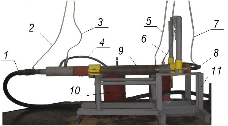 Image 12 – An experimental stand for studies starting node submersible drill: 1 - discharge hose, 2 - output speed sensor CPG 3 - output pressure sensor CPG 4 - output flow measurement CPG, 5 - output speed sensor NEC, 6 - output pressure sensor NEC; 7 - the output speed sensor with the State, 8 - output flow measurement CPG 9 - drill, 10 - measured capacitance, 11 - stand.


 (7 frames, delay 0.5 s, volume of 194kb)")
 (6 reps, 7 images,volume 134 кb)")
