
Abstract
Content
- Introduction
- 1. Subject urgency
- 2. Idea and the work purpose
- 3. State of the art review
- 4. Schematic diagram of the double water jet pump
- List of sources
Introduction
Recently growth rates of oil production, and also drinking and technical water for needs of the population and the industry raised. Tendencies to growth of depths of wells were outlined. Equipment service conditions for liquid lifting from wells thus become complicated.
For more than centenary period which has passed from the moment of creation of jet devices, will make significant progress both in the field of improvement of designs of devices, and in development of methods of their calculation. Constructive improvement of devices allowed to increase for this period their efficiency with 5-8 to 30-40 %.
The wide circulation of jet devices is caused by the following advantages: high self-soaking-up ability and possibility of pumping of the liquid containing a firm phase, small dimensions, simplicity of a design, lack of rubbing parts. Application possibility in hard-to-reach spots.
1. Subject urgency
Water jet pumps are simple on a design, are reliable, have no moving parts and valves, can pump out the polluted water. A lack of use of pumps is restriction on depth to liquid lifting – to 70-80 m. For conditions of big dynamic level possibly use of the water jet pump with two jet devices. But absence of any recommendations about an occasion of use of the similar pump constrains works in this direction.
The master's thesis is devoted to an actual scientific task creation and research of a design of the double water jet pump for liquid lifting from wells. Within the carried-out researches it is expected:
- By developed mathematical model to determine quantitative expression distribution of a stream of active liquid to a drive of the bottom and top jet pumps.
- To execute calculation of design data of jet devices of the device that will give the chance to define pressure losses in local support of the pump.
- In program system ANSYS to execute physical modeling of dynamic processes in the double water jet pump that will confirm justification of the developed mathematical model.
- Recommendations about a pump scope are developed.
Further researches are directed on the following aspects:
- High-quality improvement of the developed design.
- Delimitation of efficiency of the double jet pump.
2. Idea and the work purpose
Use of the pump with two jet devices will allow to increase depth of pumping of liquid from wells.
The work purpose – to establish laws of dynamic processes in the double water jet pump for definition of possible area of effective application.
3.State-of-the-art review
Jet pumps (hydroelevators or ezhektor) belong to group of pumps devices, i.e. pumps which operate by a principle of transfer of kinetic energy from a stream of working liquid to a stream of pumped-over liquid, thus transmission of energy from one stream to another occurs directly without intermediate mechanisms.
Jet devices received wide application practically in all branches of equipment. Their feature is increase of pressure of an injected stream without a direct expense of mechanical energy at exclusive simplicity of a design. At prospecting works widely apply the ezhektor shells which basis is the water jet pump.
Ezhektor shells of ESP type are developed for liquid pumping from boreholes in VIOGEM.
The еzhektor shell of ESP – 168/203 (fig. 1) consists of a flushing head, a set of double pipes and the water jet pump [3].

Figure 1 – ESP water jet pump - 168/203
The water jet pump consists of the case 9, the rewater-transport worker 11, the sealant case in the 12th diameter of 114 mm for connection with a column of internal pipes, the rewater-transport worker 2 for lengthening of the soaking-up pipeline by boring pipes in diameter of 168 mm, the jet device placed in the case 6. The jet pump has bringing knee 3, a nozzle 4, the chamber of mixture 7. Diffuzor 8 has diameter of an entrance opening equal to diameter of an opening of the corresponding chamber of shift. The target branch pipe of the rewater-transport worker 10 provides reliable connection with the case of a sealant of a column of internal pipes. The nut 5 fixes position of the chamber of mixture 7 concerning a nozzle 4.
Shell for drilling of wells of the big diameter, combining direct and return washing in a prizaboyny zone. The schematic diagram of such chisel tool is shown on fig. 2[3].
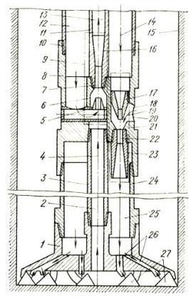
Figure 2 – The shell scheme for drilling of wells with combination of direct and return washings
The shell turns on the breed destroying tool 1, the case 8, water submitting 10, soaking up 3 and delivery 11 pipes forming respectively water bringing 12, soaking up 2 and delivery the 13th channels, the jet device 9 of return forcing consisting of a nozzle 5, chambers 6 of absorption and the mixture chamber 7 with a diffuzor 16. The jet device of 21 direct forcings is established parallel to the basic in the case 8 and consists from a nozzle 17, chambers 18 of absorption and the chamber of 22 shifts with a diffuzor 23, and nozzles 17 jet devices of 21 direct forcings is hydraulically connected to the water carrying out channel 12, the chamber 18 of absorption is connected by the channel 20 to external space, and the diffuzor 23 is hydraulically connected to the ring delivery channel 25, formed by the ring casing 24 connected by the case 8 with AT 1, containing flushing channels 26 which are directed on breed the destroying elements 27.
Shell lower in a well and on the ring channel 12 of a double column of pipes submit flushing liquid 14 in nozzles 5 jet devices 9 of return forcing. At the same time from the channel 2 soaked up liquid 4 with the destroyed breed also arrives in the delivery channel 13. The part of working liquid arrives from the channel 12 in nozzles 17 jet devices of 21 direct forcings and at an exit soaked up a part of the liquid 19 arriving through the channel of 20 from a well. Further the stream passes through the chamber of mixture 22, a diffuzor 23 both in the ring channel 25 and on flushing channels 26 the N breed the destroying elements 27 moves. The liquid stream with the destroyed breed arrives to an axis of the chisel tool and via the channel of absorption 2 and forcings 13 is taken out on a surface.
Jet pumps apply in coal industrial at methane production from coal layers. On fig. 3 hole’s jet installation for decontamination of coal layers is shown[1].
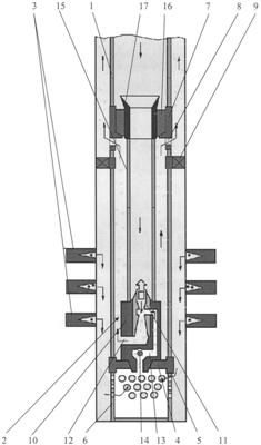
Figure 3 – Hole’s jet installation for decontamination of coal layers
On a column 1 pump and compressor pipes in a well lower established on it from below-up a boot filter 6 with the rewater-transport worker 5, the bottom basic ring 4, poker 9 and the top basic ring 7 with throughput windows 8.
In an internal cavity of a column of 1 pump and compressor pipes during its descent in a well establish the case 10 of the jet pump 2 which bottom end tightly establish on bottom to support a ring 4 and the pipe connected to it 15 with a pressurizing element 16 which establish in the top basic ring 7.
Further in a column of 1 pump and compressor pipes dump a demountable insert 11 with a nozzle, the chamber of mixture and a diffuzor which when pumping liquid in a column of 1 pump and compressor pipes passes through a pipe 15 and it is spontaneously established in the case 10 of the jet pump 2.
Then on a column of 1 pump and compressor pipes submit under pressure the working agent on a nozzle of a demountable insert and create a depression in under poker zone, and poker 9 is located above the top coal layer 3. As a result water from a face via the channel 13 of a supply of the environment pumped out from a well is fond in the chamber of mixture of a demountable insert 11 jet pumps 2 where mixes up with a stream of the working agent and together with it is taken out via the channel 12, behind a pipes space of a pipe 15 and absorbent windows 8 in behind a pipes space of a column of 1 pump and compressor pipes are higher than poker 9 and on the specified behind a pipes space arrives on a surface. In process of fall of level of liquid (water) in a well through a boot filter 6 in the jet pump 2 coal gas which also, mixing up with a stream of the working agent arrives, arrives on a surface. Thus, there is a liquid selection, including muffling liquid, and coal gas in the form of a gaz and waters mix, which is divided then into fractions in a gas tank (isn't shown on the drawing) on a surface. Changing parameters of a demountable insert 11 (for example diameter of a nozzle, by replacement of a demountable insert 11) and pressure of pumping of the working agent via the jet pump 2 it is possible to optimize parameters of operation of the jet pump 2 easily. Besides, supply of coal gas on a surface occurs compulsorily that allows to increase its output.
The pump-jet device shown on fig. 4[2], contains the engine 1, a shaft 2, the case 3 with the internal working chamber 4 and the wheel 5 placed in it, a soaking up branch pipe 6 for the injected environment which is established coaxially with a wheel 5. On an internal surface of a wheel 5 partially open sixteen cylindrical radial channels 7 with narrowing on an exit by installation of plugs 8 are executed. The wheel 5 is placed in the ring mixing block 9 containing sixteen chambers of mixture of 10 cylindrical forms with internal tumulus on an input. Thus the wheel 5 is placed in the ring mixing block in such a manner that exits of channels 7 are informed with inputs of chambers of mixture 10 by means of a ring backlash 11 between a wheel and the ring mixing block. From outer side of the ring mixing block 9 the covering ring mixing block 9 and uniting exits of chambers of mixture 10 is located diffusor 12, executed in the form of a spiral. The branch pipe 13 with tangential input of a working liquid is established before consolidation 14 shaft 2 on the party of an absorption of a wheel 5.
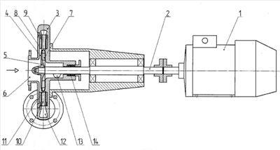
Figure 4 – The pump and jet device
Working liquid moves in a branch pipe 13 with the tangential input, established before consolidation 14 shaft 2, on reception of a wheel 5. In a wheel 5 which radial channels 7 are executed partially open a cylindrical form with narrowing on an exit a way of installation of plugs 8, at power impact on working liquid only the dynamic component of pressure in a stream of working liquid increases, and also there is a twisting of a stream of working liquid at interaction to a wall of the working chamber 4 and a surface of channels 7 of a wheel 5. Working liquid moves so that its direction coincided with the direction of a twisting of working liquid in a wheel 5.
The device for processing and research of wells (fig. 5)[7]. This hole’s jet installation allows to carry out layer researches on a depression and to make its processing by chemical reagents. However replacement of the pressurizing knot by a blocking insert that increases works time at the expense of descent lifting of inserts is necessary for performance of the specified works and reduces reliability of work of the equipment.
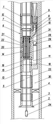
Figure 5 – The device for processing and research of wells
On a column of pipes 1 in a well lower a funnel 2 with a shaft 3, poker 4 and the jet pump 6 in which case 7 in the central channel 12 through passage in the bottom situation on a seat 13 the blocking insert 16 is established on frictional sealing elements 15, the top which lateral window 17 is combined with the channel of a supply of the active environment 10, and the bottom window 18 - with the channel 11 of a supply of the pumped-out environment. Give poker 4 into position, separating behind a pipe’s space of the 30th well on over poker’s and under poker’s. On a logging's cable 23 lower in an internal cavity of a column of pipes 1 pressurizing hub 21 and below its receiver converter of physical fields 24 thus pressurizing a hub 21 20 step channels 19 through passage have on a seat, and the receiver converter of physical fields 24 is lower than the jet pump in a studied zone of a productive layer.
The pressurizing hub 21 with frictional sealing elements 28 separates internal space of a column of 1 pipes and at the same time, at the expense of existence of the axial channel 22, doesn't obstruct to traffic of a logging’s cable 23. In a well the receiver converter of physical fields 24 make background measurements of pressure, temperature and other physical fields in space to a well face.
After submit a working environment on a column of 1 pipes to a nozzle 8 jet pumps 6 that allows to begin pumping by the jet pump 6 of a under poker’s zone of a well of a sheeted fluid. The bedded fluid on under poker’s space and the channel 11 of a supply of the pumped-out environment via the return valve 29 arrives on an entrance of the chamber of mixture 9 where mixes up with an active working environment and further on behind a pipe’s space 30 well over poker 4, arrives from a well on a surface.
The gas ezhektor (fig. 6)[8] contains coaxial nozzles 1, the reception chamber of mixture 2 and 3, a diffuzor 4, coaxial branch pipes 5, 6, disks 7, 8, profile elements 9 and 10, an additional branch pipe 11 which are reduced by hydraulic resistance. Such ezhektor can be used for pumping of gas.
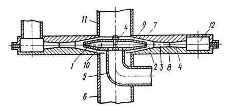
Figure 6 – Ezhektor
The active environment gets to a nozzle 1, soaks up the passive environment from the reception chamber 2 where gets through branch pipes 6 and 11. After streams mixed up, this mix arrives in a collector 12, and from there arrives to destination.
For boring with return bottom-hole washover under the offer N.S.Levchenko has been constructed for the first time a dual core barrel of jet type. On the basis of this construction constructive varieties dual, and later and unary jet shells are elaborated many. These shells are equipped by jet pumps. Showing of these shells is caused by that at backwashing a core recovery above, than at a straight line.
Are elaborated unary (UJС) and dual (DJС) the jet column shells constructing nagnetatelno-inhausting (combined) washover at well boring.
Elementary diagramme UJС is demonstrated in drawing 7 [9]. Flush fluid moves to a shell on drill-pipes from a mud pump erected on a surface. Driving through a sub with a nozzle 1, it gets to mixing chamber 3 and the diffuser 4, whence through channels 5 in the receiving camera 2 arrives in an annular gap between walls of holes and an auger system. In an annular gap the flush fluid current is partitioned on two parts: one part rises on a surface, the second – arrives to a stope back.
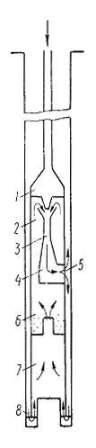
Figure 7 – The elementary diagramme of the device of an unary jet shell
At flow of fluid from a nozzle 1 in mixing chamber 3 in the receiving camera 2 there is an exhaustion that leads to infill by its fluid exhausted from a stope back through an injection drill bit 8, a core barrel 7, a sedimentation barrel 6. Rising top, fluid carries up formation fines in a sedimentation barrel, excluding thereby core jamming. From a sedimentation barrel the purged flush fluid arrives in the receiving camera 2 jet pumps. Presence in a jet shell of a sedimentation barrel preserves an injection drill bit from an abrasion drilled solids fragments.
Design UJС of construction CNIGRI is represented in drawing 8[9]. This shell is intended for boring in strongly broken up, alternating formations IX – XII categories on drillability.
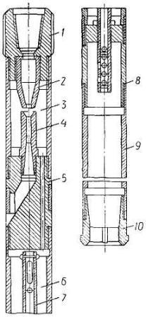
Figure 8 - Column UJС
In drawing 9 the schema of the device and operating principle DJС is resulted [9]. The Flush fluid submitted on drill-pipes from a surface under pressure of the pump, leaves a nozzle 1 in the receiving camera 2, carries away behind itself fluid being in it and is routed to mixing chamber 3 and a diffuser 4. Further it arrives in an annular gap between outboard and internal core barrels and moves to a bottom hole.
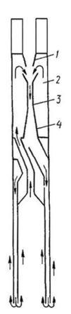
Figure 9 - The elementary diagramme of the device of a dual jet shell
On a stope back blended a current it is partitioned on the basic and эжектируемый. The basic current is routed to hole mouth in an annular gap between hole walls and a column shell, and эжектируемый through an internal core tube – to the receiving camera 2. As in the receiving camera between a nozzle and mixing chamber, under condition of feeding of the strong spray, all time is maintained vacuum from an internal core barrel fluid arrives continuously, effecting return bottom-hole washover. The blended current in dual jet core barrels forms combined – nagnetatelno-inhausting washover.
The jet column shell for hard-alloy boring of a construction KazIMSa[9], which have been taken over to a batch production, is demonstrated on fig. 10 [9]:
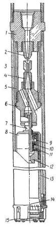
Figure 10 - DJС constructions of KazIMSa
The jet column shell for hard-alloy boring of a construction KazIMSa which have been taken over to a batch production, is demonstrated in drawing 10. The column shell consists of following basic knots and parts: the jet pump (a part 2, 4, 5), fastened on a sub 1; a distribution horsehead 6, a ball-bearing bearing (a part 7... 12); outboard 3 and керноприемной 13 tubes; керноудерживающего devices 14; a special injection drill bit (chilled-shot, hard-alloy or diamond) 15. The hard-alloy injection drill bit 15 is reinforced by chisels from hard metals of the various form. In its lateral face there are windows and outboard vertical key grooves for a flush fluid yield in exterior annular space. Such construction of an injection drill bit provides complete isolation of a core from operating of hydrodynamic efforts of a downstream of flush fluid and отчистку a bottom hole from a slime. In an injection drill bit there is a cylindrical boring for array керноудерживающего devices 14 and balancings of a core tube 13
4. Schematic diagram of the double water jet pump
At the low dynamic levels close to depth of a well, apply ezhektor shells with water jet pumps of double action. The principle of operation of the water jet pump of double action is based on a principle of operation of the jet pump.
The water jet pump of such design (fig. 11)[3] consists of a soaking-up branch pipe 1, the pump case with an external pipe 9 and internal 8, two jet devices – bottom and top – with nozzles 2 and 5 and chambers of mixture 3 and 6, diffuzors 4 and 7.
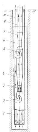
Figure 11 – The scheme of the water jet device with two water jet devices
Working liquid on the pipeline 9 gets to nozzles 2 and 5 at the same time. Because the ratio of diameter of the chamber of mixture to diameter of a nozzle of the bottom device is great, it, even at a small pressure, grasps liquid enough in relation to volume of submitted working liquid. But it has a low pressure behind a diffuzor, at the same time a pressure of its more than a height of a column of immersion of the pump under liquid level in a well. It creates favorable conditions on draw in the second step at the expense of additional expenses of energy of a stream of the liquid submitted from a surface.
When writing this paper the master's thesis is yet complete. Final end: December, 2012. The full text of work and materials on a subject can be received at the author or his head after the specified date.
List of sources
- Пилипец В.И.,
Насосы для подъема жидкости
: Учебное пособие. - Донецк, 2000. – 244 с. - Дудля Н.А.,
Проектирование буровых машин и механизмов
: Учеб. для вузов по спец.Технология и техника разведки месторождений полезных ископаемых
– 270 с. - Фридман Б.Э.,
Гидроэлеваторы
, – Москва, МАШГИЗ, 1960. – 323 с.Two authors
- Соколов Е.Я., Зингер Н.М.,
Струйные аппараты
, – М:. Энергоатомиздат, 1989. – 352 с. - Жиленко Н.П., Краснощек А.А.,
Справочник по реактивно-турбинному бурению
. – М., Недра, 1987. – 309 с.Three authors
- Добровольский Г.Б., Казикаев Д.М., Петриченко В.П.,
Крепление скважин большого диаметра
, – М.: Недра, 1988. – 238 с. - Гейер В.Г., Дулин В.С., Заря А.Н.,
Гидравлика и гидропривод
. – М, Недра, 1991. – 331 с.Four and more authors
- Дубровский В.В., Керченский М.М., Плохов В.И., Ряполов В.А., Сиднев Я.А.,
Справочник по бурению и оборудованию скважин на воду
. – М., Недра, 1972. – 511 с. - Башкатов Д.Н., Сулакшин С.С., Драхлис С.Л., Квашнин Г.П., Справочник по бурению скважин на воду.– М., Недра. 1979, – 560 с.