
Abstract
Содержание
- Introduction
- 1. Theme urgency
- 2. The purpose and objectives of the study and expected results
- 3. Justification of starting the conveyor belt
- 4. Study mode braking conveyor belt
- Conclusion
- References
- 1. Theme urgency
Introduction
Major role in the economy of our country plays industry. Ukraine has the opportunity to develop all industries. Currently running 9940 companies. The share of industry in the economy is 42%. Ukraine's coal industry - a powerful multi-industrial complex with significant production and services, multi-faceted nature of the activity of complex internal and external communications, specific operating conditions, both enterprises and workers. Currently operating in 19 state-owned holding companies, industrial associations in 8 coal, 10 separate mines, specialized holding companies and state-owned joint stock society enrichment of coal geological exploration, drilling, repair equipment, automation, communication ' communication, construction of mines and quarries, large coal plants machinery, other businesses and organizations. Obviously, such a large infrastructure is crucial to the quality and timeliness of transport and logistics operations, which, in turn, depend on the reliability of transport vehicles. Most high-performance motor type machines are machines Continuous, including belt and drag conveyors. They are widely used in the coal industry, where full or partial konveyeryzatsiya large mines provides an intensive-mining and increases productivity.
1. Theme urgency
Belt Conveyor is the most common type of transport vehicles, it serves to move the bulk and piece goods. It is used in industrial production, mines and mining, agriculture. Freight moves on the tape horizontally or at an angle of 90 ° to the horizontal, on which the dynamic performance of starting and braking conveyor belt. Start conveyors through large inertial mass and static loads significantly different duration and accompanied by significant heat engines. Overload conveyor, low voltage, some faults in mechanical and electrical equipment can cause additional delays launch process and therefore an unacceptable excess engine temperature. In addition, handling conveyor belt may slip traction element on the drive organ Thus ended the process of starting the engine does not display line on the working speed and long slipping leads to damage of the traction element, as in all cases of prolonged start-regulated pipeline over time to drive off . Therefore, to save energy, time and start-up, storage and tape drive is seen in this topic.
2. The purpose and objectives of the study and expected results
Purpose - to build and calculate mathematical model when starting or braking conveyor belt.
main objectives of the study:
- justify starting modes conveyor belt.
- study inhibition conveyor belt.
- construct a mathematical model for calculating the starting and braking modes.
object of study : Belt Conveyor.
subject of investigation : Dynamic processes at start-up and braking conveyor belt
As part of the master plan to-date research results in the following areas:
-
Get
- and calculate mathematical model of dynamic processes at start-up conveyor belt. Get
- and calculate mathematical model of dynamic processes under braking conveyor belt.
3. AJustification of starting the conveyor belt
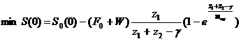
Modeling of belt conveyors start is to replace the continuous discrete models in which the relationship between point masses are replaced by elastic and dissipative connections. As a result, the model described by a system of ordinary differential equations with appropriate initial and boundary conditions. The solution obtained system - generally nonlinear ordinary differential equations - is also very difficult. Therefore, the optimal control problems starting the conveyor belt, this model has no practical application. To start solving the Laplace transform method used. As a result, found by solving the problems start conveyor belt for linear engine performance. However, in general, non-linear and discontinuous characteristics of the engine, this method is not applicable. Thus, at present there is no adequate mathematical models of dynamic processes starting conveyor belts with non-linear and discontinuous characteristics engines. To modulate the process of starting the conveyor belt using a method prypasovky (cross-linking). The essence of the method consists prypasovky that the differential equation describing the dynamic process in general solved vyhladi for each linear section aproksymuvalnoyi engine performance. Then, for a given initial and boundary conditions, which is the solution of the differential equation of the process for pre aproksymuvalnoyi linear section of the engine, are arbitrary constants of the solution to the differential equation of the process for future linear section of the engine. So consistently found a solution for all linear plots aproksymuvalnoyi engine performance.
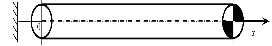
Rys.3.1 - Belt Conveyor
system of differential equations describing the dynamic process of starting the conveyor belt has the form:
the initial conditions n = 0:
Vi (E, 0) = Vx (E, 0) = 0, Wg (E, 0) = Wx (E, 0) = 0
where Wg (E, n), Wx (E, n) - dynamic components tensions on trucks and blank under the branches of a conveyor belt, H, Vi (E, n), Vx (E, n) - Load and speed points blank branches conveyor belt respectively, m / s; E, n - according dimensionless coordinates and time, and - the speed of propagation of elastic disturbances in the tape, m / s, E - aggregate tightening its belt in tension, N; p - equivalent to the linear density of ribbon kg / m (p = F / a ^ 2).
Dimensionless coordinates and dimensionless time is defined by the formulas:
E = x / L; n = at / L
where x - coordinate directed along the strip towards the head drum, with center on the axis of the tail drum conveyor, m; t - current time, s; L - length of the contour belt conveyors, c
Boundary conditions on the tail and driving drums depend on the type of clamp.
hard to clamp due to the conditions of continuity of tape are:
on the tail drum: at E = O
Vi (0, n) =-Vx (0, n), Wg (0, n) =-Wx (0, n);
on the drive drum with: E = 1/2
Vi (1/2,?) =-Vx (1/2, n)
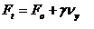
Wg (1/2,?)-Wx (1/2, n) = F (Vi) - G1 - (a * m / L) * dV / dn
where F (Vi) - starting characteristics about in terms of the F, V, N; G1 - the resistance of the belt and cargo, including skochuyuschusya because of the weight of the cargo and conveyor belt, H; m - shows the load weight over the rotating parts conveyor belt, kg.
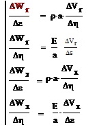
This motor starting characteristics aproksymirovalas piecewise linear spline, which can be represented as

where Ni - coordinate of the intersection of the i-th linear section aproksymovuvanoъ characteristics with the axis of OF, H; q - slope of the linear plot aproksymuvavonoyi characteristics to the axis, kg / s; n - moments of transition from one linear plot starting characteristics on the other; 6 (n) - Heaviside unit function; n - number of line plots properties.
According to Fitting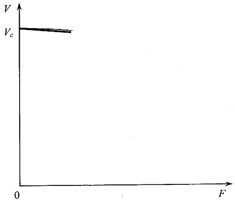
Rys.3.2 - starting characteristics over
method, we obtain the solutions of differential equations for the i-th linear section aproksymovuvanoyi engine performance.
Thus, by calculating the speed of tape on the drive drum, substituting these values, we obtain the velocity and dynamic force in any part of a conveyor belt.
4. Study mode braking conveyor belt
Extreme tension band and the worst conditions in the drive clutch (brake) drums may occur during braking assembly. This applies primarily to the inclined conveyor with negative height difference between the final reel (mine is bremsberhovyh conveyors). If the drive belt and brake unit located in the main part of the assembly line, the braking of the drive belt on the upper branch of the loaded belt begins to spread straight wave, which reduces the initial tension of sustainable regime. In conveyor tensioning device with a rigid but lower branch extends straight wave dynamic stretching, if the pipeline is installed yielding clamp (see Figure 1, b), then the wave is absent and the carriage clamp is moved in the direction of the drive. Since the bremsberhovyh conveyors with an angle settings -3 ... more -5 ° engine works in generator mode and at the point of incidence on the tape drive has minimal tension, then the further reduction of this tension can be depleted stock clutch on the drive and begin full slip tape that can cause emergency Cream of tension Feed may fall below the level at which the constant movement without the formation of unacceptable deflections between rolykooporamy As you move from mode to mode sustained inhibition of the resistance movement direction does not change, then the velocity of wave propagation. Direct waves partially reflected from the boundary loaded and empty plots ribbons, signs and reflection coefficients of the reflected waves.
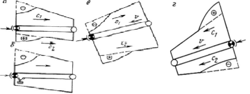
Rys.4.1 - propagation braking assembly: a, b - horizontal yoke slope, g - bremsberhovomu
schemes for tensioning device with a rigid tension at the point of incidence is at least one time calculation formula is:
 where
where
 - to complete the rim of the drum braking force; y - the slope of the mechanical characteristics of the braking device; W - traction drive at steady state (in generator mode - negative)
Maximum braking tension laden bremsberhovom belt occurs in the tail of the belt through after initiation of braking:
- to complete the rim of the drum braking force; y - the slope of the mechanical characteristics of the braking device; W - traction drive at steady state (in generator mode - negative)
Maximum braking tension laden bremsberhovom belt occurs in the tail of the belt through after initiation of braking:
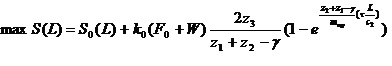
where Ko - coefficient which takes into account the reduction in the amplitude of the direct wave due to internal friction in the film as it spread to the tail assembly. For circuits with pliable tensioning device at the point of minimum tension incidence depending on the wave reflected from the boundary of trucks and empty branches tape. To analyze the stability of the belt on the roller puts in braking mode to determine the dynamic tension bands at various points along the length of the pond. When distributing the direct wave motion easing tension along the branches loaded tension at a point remote from the drive to the distance x, starts to fall over time after the braking and the time of arrival at the point of wave roztyahnennya.Tomu
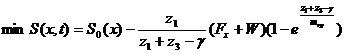
where
Stability condition holds, if
where Lp - distance between rolykooporamy laden branches to solve the problem of resistance bands on the roller puts during the period of inhibition requires very cumbersome analysis of wave processes, so these calculations should be performed with the help of computer technology, especially with complex profiles pipeline route. When you install a drive belt bremsberhovom in the zone of maximum static tension after application of braking force on the loaded branches spreading wave of dynamic stretching. Therefore, this scheme is better in terms of stability of the loaded tape during braking also as drive installed in the zone of maximum tension easily provide the required margin grip on the driving drums and no slip tape when dynamic tension near the drive reaches extreme values. For the same reasons, sometimes bremsberhovyh conveyors scheme used when the drive is set in the main part of the belt, and brakes - on the tail drum. In bremsberhovyh conveyor with brake device installed at the main station line in the area of ??minimum static tension, no slip tape can be achieved only at considerable margin grip on the brake drum, making it necessary to increase the tension in the belt loop steady state, folders need for more robust tape.
1) Start conveyors through large inertial mass and static loads significantly different duration and accompanied by significant heat engines. Overload conveyor, low voltage, some faults in mechanical and electrical equipment can cause additional delays launch process and therefore an unacceptable excess engine temperature. In addition, handling conveyor belt may slip traction element on the drive organ Thus ended the process of starting the engine does not display line on the working speed and long slipping leads to damage of the traction element, as in all cases of prolonged start-regulated pipeline over time to drive off . 2) A mathematical model on which can be calculated dynamic forces at start-up conveyor. 3) A mathematical model on which can be calculated dynamic forces during braking pipe.
When writing this master's work is not completed. Final completion: December 2011. Full text of and materials can be obtained from the author or his manager after that date.
References
1. Бужинский И.А. Определение рациональных пусковых характеристик привода наклонного ленточного конвейера / И.А. Бужинский, Р.А. Кирия// Машины для предприятий горной промышленности. – К., 1986. - с.30-38
2. Кирия Р.В. Влияние типа натяжного устройства и места его установки на динамику пуска ленточного конвейера / Р.В. Кирия, В.Ю. Масютенко, И.А. Бужинский// Сб. науч. тр. Геотехническая механика – Д. -2006. – Выш. №67. – с.73-83.
3. Попов Е.П. Теория нелинейных систем автоматического регулирования и управления. – М., 1988. – 256с.
4. Спиваковский А.О. Теория ленточных конвейеров/ А.О. Спиваковский, В.Г. Дмитриев. – М., 1982. – 192с.
5. Штокман И.Г. Динамика тяговых цепей рудничных конвейеров. – М., 1959. – 304с.
6.Галкин В. И. , Дмитриев В. Г. , Дьяченко В. П. , Запенин И. В. , Шешко Е. Е.Современная теория ленточных конвейеров горных предприятий. Учебное пособие; М.: Горная книга, 2011. - 544 с.