
Abstract
Content
- Introduction
- 1. The importance of the subject
- 2. Purpose and the tasks of the project
- 3. The economic basement of the administrative-trade complex electric supply scheme choice
- 4. Increasing power efficiency of the sub-district pump station in the way of Frequency Transformer installation on the pump electric engines
- 4.1 The Choice of a Frequency Transformer in the Pump Stations of CHS of the Communal Sphere
- 5. Comparison on security and functional capabilities of ARI with voltage 0,4 kW on electric contactors with microprocessor ARI of "Moeller" concern
- 5.1 ARI on contactors
- 5.2 General characteristic of ARI devices developed by "Moeller"
- 5.3 New possibilities for ARI devices design
- Conclusion
- List of literature:
Introduction
In the present master’s paper we consider the electric supply of the administrative-trade complex (ATC) which consists of: the head office of the telephone connection company PJSC "Ukrtelecom", administrative-trade center (ATC) "Continent" and the shop "Eldorado".
Two variants of the outside electric supply are studied: the first variant consists of a radial and two-ray scheme without distribution point (DP), the second is analogical, but with a DP. From two variants the most economical one is chosen.
Also in the way of the frequency transformer installation on the pump electric engines there will be increased the power efficiency of the micro-district pump station, where this administrative-trade complex is situated. There will be performed a comparison as for reliability and functional facilities of the automatic reserve input (ARI) with the voltage of 0,4 kV on the contactors with microprocessor ARI.
1. The importance of the subject
Now, in the conditions of private ownership, as never before it is important to have correct and economically favorable projects of separate buildings, premises, as well as big complexes which may include three and more buildings, such as: shopping centers, trade-entertainment centers, cinemas, restaurants, office buildings, hospitals, educational establishments.
The developer (a private entrepreneur) is interested in relatively cheap, quick and reliable projecting the outside and inside power supply of the complex.
Though it is necessary to understand, that reliability, electric and fire safety, constant electric supply depend directly pro rate on capital investments amounts, given for the project.
Under outside electric supply we understand the transformation sub-stations supply schemes TP 10/0,4 kV from GPP.
Under inside electric supply we understand distribution net 0,4 kV: cable (from TP till the entrance DP of the building), distribution power (supply for passenger and load lifts, escalators; supply of water pumps with hot and cold water if the building is more than 9 floors or of 1 kind), switchboard (from the entrance DP till the group light shields (LS) and from LS according to the groups to lamps).
Also, due to the customer’s request, in the project there will be foreseen an installation of the diesel generator on the tires 0,4 kV of TP2 – of the head office of the telephone connection company PJSC "Ukrtelecom". Then this building can be classified as the building with the special electric supply category, which has a preserved sub-station in the kind of an autonomic power source.
2. Purpose and the tasks of the project
The purpose is reliable, constant and qualitative projecting the electric supply of the administrative-trade complex (ATC), which consists of: the head office of the telephone connection company PJSC "Ukrtelecom", administrative-trade center "Continent" and shop "Eldorado".
The main tasks:
- The choice of the outside electric supply of АТC.
- Increasing the power efficiency of the sub-district pump station.
- Comparison as for reliability and functional facilities of ARI with voltage of 0,4 kV on the contractors with microprocessor ARI.
3. The economic basement of the administrative-trade complex electric supply scheme choice
In the present part the economic choice of the administrative-trade complex electric supply scheme is studied (1 variant is the scheme with a distribution point (DP), 2 is without DP) where there are included: the head office of the telephone connection company PJSC "Ukrtelecom" – TP2 (the calculated power is Sр=265,06 kV, I and II category of power supply, power coefficient cosφ=0,92), administrative-trade center "Continent" - ТP1 (Sр=1129,77 kV, I and II category of power supply, cosφ=0,91), shop "Eldorado" - ТP3 (Sр=366,16 кВт, I, II category of power supply, cosφ=0,93) [1].
The further schemes and calculations are presented in the my article.
4. Increasing power efficiency of the sub-district pump station in the way of Frequency Transformer installation on the pump electric engines
Using frequency-regulated drive in pump, ventilation and compressor installations allows sufficient reducing energy consumption in industry and agriculture [2].
Electric power economy is especially sufficient in the cases when the supply main value is not constant, but varies in different measurements. Invested into frequency-regulated electric drive funds are covered very quickly and make sufficient economy with the time passed.
Except the electric power economy, the frequency-regulated drive has a great number of other advantages (the hydro-strikes and moment strikes possibility is lessened, the term of equipment service is increased) [2].
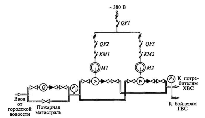
Figure 1 – Building water supply system.
All six devices are installed on one kind pumps of cold water supply (ХВС) of type КМ 80-50-200 with nominal pressure 50 мм. wat. st. and nominal productivity of 50 м3/h, equipped with a-synchronic short-circuited electric engines of type 4АМ16052ЖУ2, 15 кV, 380 V, 29 А, 2900 r / min.
The scheme of switching on the aggregates is parallel (fig. 1), one of the pumps is in operation, the other on is in a reserve. Each of the pumps is put into operation after 15 days, due to this equal wear is reached and compression and rotation valves capacity is kept. Fire way is usually closed and is opened only in a fire case.
In residing buildings, shopping centers and administrative buildings contactors КМ1 and КМ2 switching on and off is carried on automatically through the automatic blocks, control of which is performed from the contact manometer, installed in this case at the out-going way. But in the administrative buildings it may be carried on by the persons on duty.
Energy saving devices with frequency transformers (FT) add the existing scheme (fig. 1) and are switched on between the line automatic pump QF2 output and the line contactor pumps КМ1 and КМ2 inputs (fig. 2).
Running the pumps for the operation personnel was left without changes. In case of putting into operation one of the frequency transformer defend (over-loading at the current, increasing or lessening the pressure, over-heating and other) it is automatically switched off from the circuit by the contactors КМ22 and КМЗЗ, and the pump engine power supply is performed directly from the circuit through the shunt contactor КМ 11 [2].
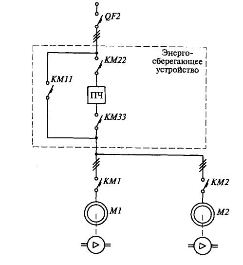
Figure 2 – a fragment of the water supply system with an energy-saving device.
The typical FT structure is presented at fig. 3. It consists of a non-regulated rectifier (В), which is supplied from the circuit, at the output of which through the condenser (С) a three-phase regulated autonomic voltage inventor is installed (АИН), which feeds the a-synchronic engine (АД) with the regulated frequency voltage. Operating the АИН keys (their switching on and off) is performed by the micro-processor panel control (БУ) [3].

Figure 3 – The scheme of frequency transformer system – a-synchronic engine.
Modern FT meet the high technical standards and guarantee a soft programmed engine input, smooth and economical speed regulation within a broad range, a high and constant voltage coefficient, good usage of the engine, high exploiting qualities – system reliability and sufficient noise reduction [4].
The majority of FT of common use have the following functional possibilities:
1) controlling due to the analogue / digital input;
2) hand/automatic running;
3) frequency range till 400 Hz;
4) possibility of forming low typical dependencies U/f (from 1 to 16 variants);
5) possibility of a vector control (running) (on the customer’s request);
6) problems diagnostic both of the transformer and the engine.
The frequency transformers are supplied with the big set of defense [4]:
1) from immediate voltage increase;
2) from over-loading along the circuit;
3) from high/low voltage;
4) from losing the phase – electronic;
5) from the engine over-heating – electronic, programmed;
6) from transistor radiator over-heating above 70 ... 85 ° С;
7) from a sudden АТ stop – electronic, programmed.
4.1 The Choice of a Frequency Transformer in the Pump Stations of CHS of the Communal Sphere
The particularity of work regimes of the cold and hot water supply pumps is in the fact that the water usage is determined by the consumers, but is not given by obligations. Regulating the electric engine speed it is possible to change the pressure created by the pump.
The economic effect can be determined on the basis of the measurements and calculations in the following way [2]:
1. In the hour of the maximum water usage (13-15 hour in the administrative buildings) the pressure is measured (mm. w. st.) at the input and output of the pump according to the manometers, installed in the system. During one (or two) hour some measurements are performed, their results are made average.
2. In the same conditions the electric engine current, А, is measured with the help of measurement pincers or Ampere-meter, if it is installed. Some consequent measurements are performed, their results are made average.
Then the ratio is checked: I < Iном.
1. The average usage for a day is measured , m³/h, according to the difference between the usage-meter indications at the beginning and at the end of the controlled day:
2. The minimum required general pressure is calculated according to the formula:
where: C = 3 – for standard buildings; C = 3,5 – for higher comfort buildings and administrative buildings;
D = 10 – for separate buildings and shopping centers; D = 15 – for a group of separate buildings which are served by CHS;
N – a number of floors, together with a basement.
3. The required pressure which is supplied by the regulated pump is estimated:
4. The required frequency transformer power is determined:
The pump aggregate CCD meaning is determined due to the formula:
5. The price of the electric power annual economy, UAH/year, is determined according to the formula:
where: ![]() – electric power, saved for a year, kW * year;
– electric power, saved for a year, kW * year;
![]() – a number of the equipment work hours for a year;
– a number of the equipment work hours for a year;
![]() – price for 1 kW*year of electric power, UAH.
– price for 1 kW*year of electric power, UAH.
6. The price of water annual economy is determined, UAH/year:
where: ![]() – water, saved for a year, m³;
– water, saved for a year, m³;
![]() – price for 1 m³ of water, UAH.
– price for 1 m³ of water, UAH.
![]() ,
, ![]() – pressure which is provided by the working pumps of CHS.
– pressure which is provided by the working pumps of CHS.
7. The annual heat economy is determined due to hot water usage reduction Gkl/ year:
where: С = 1,0 – water heat capacity coefficient, kal / g, ° С;
Δt – the calculated temperature range due to over-heating the hot water, ° С;
![]() – water, saved for a year, t.
– water, saved for a year, t.
For typical CHS in calculations the hot water usage is taken as 0,4 from the general water usage which is supplied by the working pumps.
The price of the annual heat economy is determined, UAH/year:
where: ![]() – price for 1 Gkl of heat, UAH.
– price for 1 Gkl of heat, UAH.
8. The approximate term for additional equipment expenses cover (ТОК), year:
where: ![]() – costs for the additional equipment FRD, including its installation.
– costs for the additional equipment FRD, including its installation.
There was performed a previous calculation, its data are presented in table 1.
| Parameter | Identification | Measurement unit | Meaning |
|---|---|---|---|
| Minimally required general pressure | |
mm. w. st. | 43,00 |
| The required pressure which is provided by a regulated pump | |
mm. w. st. | 18,00 |
| Coefficient which considers the pump aggregate CCD change at changing the average day costs | |
r.u. | 0,89 |
| Pump aggregate CCD | |
r.u. | 0,8 |
| Required power of the frequency transformer | |
kW | 4,73-5,16 |
| Electric power annual economy | |
kW*h | 2093,79 |
| Electric power annual economy price | |
UAH/year | 5234,48 |
| Annual economy of cold water | |
м³ | 3679,20 |
| Cold water annual economy price | |
UAH/year | 66225,60 |
| Annual heat economy due to lessening hot water usage | |
Gkl/year | 44,15 |
| Annual economy heat price | |
UAH/year | 13245,00 |
| Total annual economy | |
UAH/year | 84705,08 |
5. Comparison on security and functional capabilities of ARI with voltage 0,4 kW on electric contactors with microprocessor ARI of "Moeller" concern
Effective method of increasing of power supply security is usage of the automatic reserve input (ARI). Apart from this in EIC there is mentioned that "Electrical receiver of first category of power supply are to be provided with electric energy from two independent mutually reserved power sources, and interruption of their power supply can be made only for the period of automatic restoration of power supply", i.e. there is express indication for necessity of ARI devices usage [5].
5.1 ARI on contactors
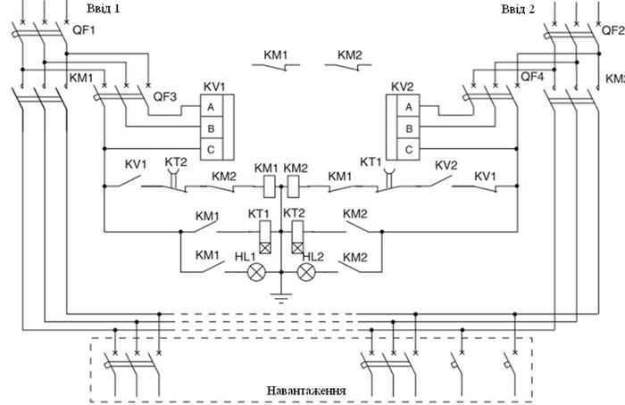
Figure 4 – Scheme of ARI with voltage 0,4 kV on contactors
Operative automatic switching in ARI device is made with regulated time interval by change of phase sequence, asymmetry of phase voltage, absence of one or more phase, symmetrical voltage reduction, emergency mode of short circuit of main and reserve introduction of supply mains [1].
On scheme (figure 4) there are two three-phase voltage relays of type PHПП-301. These relays are designed for the most responsible consumers, and are used in ARI devices.
Relay PHПП-301 provides:
– opportunity to select two modes of means voltage control: switching from phase voltage control to line voltage control;
– control of available level of current value of phase/line voltage and operation under current voltage value;
– independent control of installations under minimum/ maximum voltage;
– control of right phase sequence;
– control of full phase and symmetry of means voltage with regulated installation under phase imbalance;
– control of state of magnetic starter power contacts before and after energization;
– loss of load 380V/ 50Hz by the way of disjunction of power supply circuit of magnetic starter coil (commutation of electric circuits of direct and alternate current) under arising of conditions for operation with time interval set by consumer;
– control of means voltage quality after loss of load and its automatic switching-on after restoration of voltage parameters with time interval for automatic reclose set by consumer;
– individual indication under every type of mains voltage accidents and non switching of magnetic starter power contacts; indication of mains voltage.
ARI on contactors has row of drawbacks:
1) low reliability of electromechanical units of relay;
2) increased quantity of contact connections;
3) low operability, i.e. it cannot be supplemented with additional functions;
4) big size;
5) except this, necessity of realization of any additional function leads to significant complication of scheme, and consequently to increase of size.
Thus, having analyzed drawbacks of this scheme, I install microprocessor ARI.
5.2 General characteristic of ARI devices developed by "Moeller"
ARI devices of "Моeller" concern for nominal voltages from 40 to 6300 A are made on the basis of closing switches "Моeller" series NZM, PMC and IZM. Work control is performed by programmed relays series EASY.
Devices are designed under principle of "open scheme" which allows further extension of performed functions. There has been provided possibility of setup by user (under password) of time intervals for operation by switching on and switching off of ARI closing switches [6].
Under request of customer ARI device can be made:
– in casing with protection level IP54 (Fig. 5);
– without casing for assembly of distribution unit on doors;
– for assembly with possible visualization with the help of multi-functional display MFD-Titan.
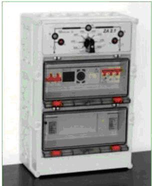
Figure 5 – ARI device of "Moeller" concern in casing
Control relay EASY saves algorithms of voltage control on inputs, their priorities, electrical blockings and power circuit breakers control. In ARI device cabinet (fig.5) there is situated function switches, and also light alarm of closing switches state and availability of voltage on every input. ARI device can be operated both in automatic and manual control mode (there is special switch).
Securing of proper functioning of ARI devices is guaranteed on two levels:
– every change of closing switches state is possible only after switching of additional contacts of switch, which was operated earlier;
– obligatory delay time before execution of the next program step.
There are manufactured three following typical schemes: ARI device of type ZA 2.0, ZA 2.1, ZA 3.0.
Device ZA-2.0 (fig. 6) provides power supply of voltage (nonsectional bus bars) from two independent inputs U1 and U2 [6].
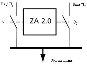
Figure 6 – Flow chart of device ARI ZA 2.0
In case of voltage loss on main input U1 closing switch Q1 switches off input U1 over time interval T1 which can be set. After switching off of U1 over time interval T2 which can be set closing switch Q2 switches on, connecting bus bars to reserve input U2.
By voltage recovery on main input in time T3 which can be set, switch Q2 switches off, and over time interval T4 switch Q1 switches on, again connecting bus bars to reserve input U1.
Time for all four time intervals T1-T4 which can be set can be changed within range from 5 to 15 seconds.
Thus, in device ZA-2.0 there is realized ARI on input with fixed priority of U1 input and time intervals T1-T4 which are fixed.
Device ZA 2.1 (fig. 7) provides power supply of two voltages (sectional bus bars 1 and 2) from two independent equal inputs U1 and U2 [6]. By this ARI device manages work of three closing switches Q1, Q2 and Q3.
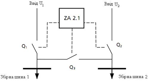
Figure 7 – Flow chart of device ARI ZA-2.1
In case of voltage loss (for example on input U1) closing switch Q1 switches off over time interval T1, and then switch Q3 switches on over time interval T2. At this bus bar 1 is connected to input U2 via bus bar 2.
By recovery of voltage on input U1 over time period T3 which can be set, closing switch Q3 switches off and over time interval T4 switch Q1 switches on, again connecting bus bars 1 to its input U1.
Likewise works device by fault of input U2 (having corresponding time intervals T5-T8). The range of possible values for time intervals T1, T2, T5 and T8 amounts from 5 to 10 sec, for T3 and T4 – from 5 to 15 sec, and for T6 and T7 – from 8 to 15 sec.
Thus, in device ZA 2.1 there is realized sectional ARI with time intervals T1 – T8 which are fixed.
Device ZA-3.0 (fig. 8) provides power supply of nonsectional bus bars from three independent inputs U1, U2 and U3 (the last one is as a rule independent source) [6]. Program of device`s work which is integrated into relay series EASY, allows selection of any input as main one. Choice of priority input is made by special switch, situated on front panel of device.
If at first moment there is voltage on input which was selected as main, than over time period T1 corresponding switch will connect bus bars with this input.
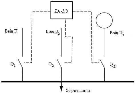
Figure 8 – Flow chart of device ARI ZA-3.0
By fault of main input, over time period T2 it is disconnected from voltage. If at this moment there is voltage on reserve input, then the latter switches on over time period T3. In case of power interruption reserve input switches off over time T4.
In case of absence of voltage on main and reserve inputs bus bars are connected to second reserve input over time interval T5. By recovery of voltage on one of the first two inputs third input switches off over time interval T6, and main or reserve input switches on over time period T1 or T3 correspondingly.
The range of possible values for time intervals T1, T2 and T5 amounts from 5 to 10 sec, for T3 and T4 – from 5 to 15 sec, and for T6 – from 8 to 15 sec.
Thus, in device ZA-3.0 there is realized triple ARI on input with changed priority of inputs and time intervals T1-T6 which are fixed [6].
5.3 New possibilities for ARI devices design
Every year demands to security of power supply are increased. And the main method of its increasing is usage of the automatic reserve input (ARI). The main unit of every such device is control module. In sub-clause 5.2 we became acquainted with standard control modules of ARI, realized on basis of EASY relay. But in connection with increasing demands to functional intension, and also to provide difficult algorithms of work with possibility of manual and remote control, there is arisen necessity to use more improved devices such as for example visualization panel with inbuilt PLC XV.
Control modules ZA on the basis of EASY relay are intended for managing ARI devices in which closing switches NZM, LZM and IZM rated at current up to 6300 A [6]. Flexibility of program allows operative changing of time settings for switch to reserve, clearance, priority of input, and also introduction of additional function of manual control or additional blockings (for example in case of fire). Blockings permit construction of ARI devices for two inputs without sectioning (ZA-2.0) and with sectioning (ZA-2.1), and also ARI for three inputs without sectioning (ZA-3.0).
The use of visualization panel with function PLC series XV as operating element in control modules allows expansion of functional capabilities of ARI devices to a considerable extent, and also realization apart from abovementioned schemes of more complicated schemes, such as fox example, three inputs and two section devices or ring circuit for power supply of three or more inputs [7].
Examples of realization of ARI schemes on the basis of unit ZA-3.2, ZA-4.1, ZA-3.3 are presented on figure 9.
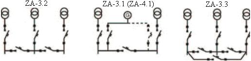
Figure 9 – Schemes of ARI devices: a) ZA-3.2; b) ZA-4.1; c) ZA-3.3
Managing of motor-drives is performed via output modules. By use of analyzers of network parameters which recently are used very often in input sections, information about state of inputs can be obtained immediately via Modbus-RTU or Profibus Protocol. In such a case there is no need to use phase control relay and there are occurred following possibilities: displaying of operative data about state of inputs to panel display; interactive adjustment of all operating levels of ARI both under time and voltage, frequency and so on; readout of this information via remote computer.
By usage of closing switches IZM with universal breaker, measuring module IZH-XMH and connection module IZM-XCOM-DP as commutation device, there is no need to use phase control relay and network analyzers, because closing switch itself performs all necessary measurements. Also there is no need to make assembly of management circles, because backward management of closing switches also is fulfilled via Profibus-DP bus bay.
Structural scheme of ARI device with usage of XV panel and closing switches IZM (management via Profibus) are presented on figure 10.
Apart from main function ARI, including blocking, such system provides great variety of additional function [7]:
1) technical accounting of energy on inputs;
2) protocolling of events under time (switching offs, undervoltages, voltage depressions);
3) readout of state of every closing switch (quantity of commutations, operation in motor hours, temperature, state of components, readiness, location in basket, etc);
4) warnings about all alarm modes of network and loads;
5) remote displaying on personal computer via OPC client or doubling of panel`s display;
6) displaying of full information about every input (voltage, currents, cos?, power, frequency);
7) interactive adjustment of temporary parameters and switching thresholds of ARI;
8) interactive manual ARI management.

Figure 10 – Structural scheme of the device ARI running through the network Profibus
(animation: 6 frames, 7 cycles of recurrence, 76,8 kilobyte)
(IZMN2-U3200, IZMN2-U3200 – automatic breakers, IZM-XCOM-DP – communication unit, Profibus-DP – network connecting switches ARI with panel visualization, XV-230-57-MNP-1-10 – panel visualization, Ethernet – optical cable, connecting the visualization of remote computer)
Use of panels provides opportunity for further modernizations and connection of other devices to Profibus network. For example, in future it will be possible to connect automatic feeder switches NZM with electronic breakes and units NZM-XDMI612 to network. At this it will become possibly to control outgoing lines, and upon availability of measurement module on input device to make technical accounting on every line. By connection of input-output units there is also possible to maintain control by motor – drives of outgoing line automations or contactors. Integration of contactors management system SmartWIRE to Profibus network is also possible.
Conclusion
In 3 section there has been considered economic choice of the scheme of power supply of administration and trade complex.
There were calculated basic technical and economic indicators of compared variants. The calculation showed that cheaper turned out to be the second variant.
Also there has been evaluated the economic efficiency of compared variants: the number of saved electricity was 7662,5 thousand kWh, the cost of saved electricity – 7.663 thousand UAH/year, the difference in charges for maintenance and amortization for overhaul – 14.8 thousand UAH/year balance sheet profit amounts (-7.137.) UAH/year.
The considered variants differ in the length of cable used, electricity losses and the number of used single-end service assembled chambers. Cable cross-section, the number and capacity of transformers is the same. Although the loss of electricity in a more expensive variant I is less (which in some cases might have an advantage during operation). But calculations showed that the balance sheet profit is negative, so the cheaper variant II is selected. Because the for the payback period of the varinats of electrical equipment (4 years), variant I do not compensate due to lower losses of the electric power cost of variant II.
In section 4 there has been calculated economic effect of the installation of frequency converter (FQ) on pump motors. The annual cost of heat saving amounted to 13245,00 UAH/ year, total annual savings – 84705,08 UAH/year.
As the economic effect of the FQ installation has exceeded all expectations, as well as FQ meets the highest technical requirements and provides soft program start of the engine, smooth and efficient regulation of speed in a wide ranges, high and stable power factor, high performance – reliability of the system and considerable reduction of the noise, without any doubt, installed it on pump motors.
In section 5 there was made the comparison under reliability and functionality of the ARI with voltage 0,4 kV on contactors with microprocessor ARI.
Because the microprocessor ARI are easier to operate and more reliable than ARI on the contactors (no mechanical contacts; easy setup; check the less operative circuits, because instead of them there is program for adjustment), I install them on the bus bars 0,4 kV of all transformer substations administrative and trade complex.
List of literature:
1. Справочник по электроснабжению и электрооборудованию: в 2 т. Т. 1. Электроснабжение./ Под общ. ред. А.А. Федорова.—М.:Энергоатомиздат, 1986. — 568 с.; ил.
2. Насосы, компрессоры и вентиляторы. Шлипченко З.С., К., «Техніка»», 1976. — 368 с.
3. Справочник по преобразовательной технике. Под ред. И.М. Чиженко. К., «Техніка», 1978. — 447с. с ил.
4. «Кабель инвест» [Электронный ресурс]. Режим доступа: http://www.ci.kiev.ua/node/34.
5. Правила устройства электроустановок. – Х.: Изд-во «Форт», 2009. – 704 с..
6. «Elsnab. Электротехническое снабжение» [Электронный ресурс]. Режим доступа: http://www.elsnab.ru/moeller/modulnye_pribory.html.
7. «Промышленные системы» [Электронный ресурс]. Режим доступа: http://www.04kv.com/text/art_av .