Abstract
Content
Introduction
Tactile perception is the widest human organ of senses as the tactile cells are all over the body on the skin and mucous coats. Tactile perception along with the other types of human senses is a very important element for full physical interaction of a person with the environment whether this is walking, running, sitting on a chair, avoiding obstacles, manipulating with objects or using different objects , interacting with other agents. In every of the above mention interaction tactile perception serves to define the conditions of the contact between the acting agent and the environment or other agents. In a general sense, tactile perception describes the measurement of a great number of conditions of interaction between two planes including a contact zone, pressure, temperature, shearing and texture. In reality, that is what a human tactile system fulfils to define different types of physical interaction, which a man has to deal with during the interaction of the skin and the environment.
Rationale
Robotic and artificial intelligence systems have been actively developing for the last decades. Robots are designed not only to imitate the human physical actions but also to help a human in its activity, to solve different applied tasks. When creating such systems the methods based on the simulation of the peculiarities of perception, processing and information presentation are used. Tactile interaction is one of the crucial either robot – man or robot – robot interaction.
Application of artificial skin in robotics helps adapt robot behaviour to external forces, improve its dexterity and intellectual interaction, which arise in the process of the interaction of a robot with environment and a man.
Tactile sensors can be used in different spheres dealing with artificial skin for robots - in medicine, prosthetic care, rehabilitation, safety devices, human-machine interface, automation, virtual reality and so on.
Purposes and tasks of the investigation
The purpose of this master's degree work is to investigate and develop the prototype of the artificial skin suitable for covering the parts of the anthropomorphic robot body.
The main stages of the investigation are:
- The bibliographical review of existing approaches and systems of artificial skin realization;
- Selection and justification of the artificial skin system selection;
- Development and adjustment of the hardware part;
- Development of new and modification of existing models of neural networks to process the data and receive the images of distribution of pressures on the artificial skin;
- Experimental investigation of the developed artificial skin prototype.
Theoretical and practical results of the work, the developed artificial skin prototype are to be experimentally estimated on the real robots in the laboratory ETIS in Université de Cergy Pontoise, France.
Overview of the existing artificial skin systems
Development of tactile sensors suitable for application as artificial skin for robots is an actual problem for robotics and a lot of scientists mainly from Europe, America, Canada and Japan are investigating this problem.
The tactile sensors for geometric recognition of the objects in the environment were designed due to the development of the robotic engineering. The main tendency in the sphere of tactile sensors creation is to simulate the tactile properties of human skin. Matrix type tactile devices meet this tendency to the upmost degree as each matrix cell, which is in essence a microelectronic force (strain or torque) sensor gives definite information making it possible to form a full image about an object shape.
Tactile sensors are classified depending on their operating principle and physical nature. According to the operating principle tactile sensors can be resistive, capacitive, inductive, optical, magnetic, piezoelectric, ultrasonic, and electromagnetic. According to the physical nature they can be flexible, elastic, rigid and so on.
Modern tactile sensors for robots should have the following properties [1]:
high sensitivity, ability to perceive pressure (force) and to transform it into electric signals enabling to define an object shape and material;
high space resolution;
perfect linear characteristics (only the deviations which can be compensated by computer signal processing are permitted);
negligible hysteresis;
tolerance to overloads and heavy operating conditions;
small dimensions and weight;
minimum number of wires in the sensitive zone;
simple procedure of wiring and connections;
low cost.
The description of different types of tactile sensors is given below [2]:
Resistive sensors usually consist of two conductive layers separated either with air or wit non-conductive material. They operate on the resistive principle. They can be of two types: a) resistance depends on the point of force application; b) resistance depends on the amount of the force applied. Resistive sensors are sensitive and cheap but they are energy- consuming. Another drawback of this sensor type is that they can define only one contact point.
Piezoresistive sensors are made of materials whose resistance changes with force /pressure. The system based on the sensors of this type was used to create an anthropomorphic arm [3]. Force sensing resistors (Figure 1) based on the piezoelectric effect are widely used in devices defining the positions. They are widely used due to their low cost, simple electronics and high sensitivity. They are used in many experimental tactile systems [4]. Their drawbacks are: they require high- technological manual or series assembly, possess non-linear response and hysteresis, are manufactured on the comparatively rigid base plate.
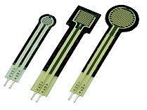 Figure 1. Force sensing resistors FSR.
Tactile sensors made of composite materials are based on the Quantum Tunnel Composites effect (QTC). Composite materials consist of metal particles and a non-conductive rubber adhesive element. QTC has the unique capability of transformation from a virtually perfect insulator to a conductor when a force is applied to it: compression, deformation, twisting and stretching of the material. The insulator - conductor transition has an exponential dependence.
Capacitive tactile sensors consist of a plate capacitor in which the distance between the plates or its effective area changes when applying the force by changing the position. Distance change results into the change of a capacitor electric capacitance. This type of sensors can be very small in size which permits to build up a sensor array (Fig. 2, 3, [5]), and to make measurement in dynamics. They have high sensitivity, spatial resolution and quick response, high interference immunity and can be placed on the fingers of a robot of any construction.
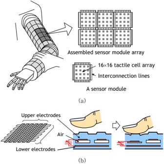 Figure 2 – Schematic diagram of a modular expandable capacitive sensor: (а) sensor module array, (b) structure of a sensor cell. Tactile sensor capacitance changes depending on the air gap when the force is applied.
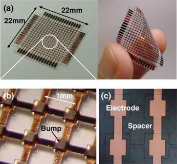 Figure 3 – (а) Ready-made module of a tactile sensor , (b) cell enlarged image, (c) lower electrodes and a spacer.
Optical tactile sensors are based on changes in material optical properties under the influence of a force applied to the material. Optical sensors can measure force as low as 0,001N with the spatial resolution 5 mm [6]. Optical tactile sensors are immune to electromagnetic interference, are flexible, sensitive and fast but at times they are bulky.
Acoustic ultrasonic sensing is yet another technology which has been used for the development of tactile sensors. The main component of an ultrasonic sensor is an electro- acoustic transducer and a piezoelectric ceramic element is often used in this function. As the same transducer is used to transmit and receive the signals, to define the objects in the nearest zone the quick damping of acoustic energy is required. This can be achieved by using acoustic absorbers and decoupling between the transducer and the body. The body design permits to receive a narrow acoustic streaming which gives a powerful directional signal. The advantages of such sensors are quick dynamic response and high resolution.
Magnetic tactile sensors are based on the principle of the density measurement of the stream cause by the applied force. The flux measurement can be made by either a Hall Effect [7], or a magneto resistive device. The tactile sensors based on magnetic principle have a number of advantages that include high sensitivity and dynamic range, no measurable mechanical hysteresis, a linear response, and physical robustness. Major drawback of magnetic based tactile sensor is that they cannot be used in magnetic medium.
The piezoelectric sensor operation is based on the property of some crystals to generate charges when compressing or stretching. The example of such crystals is quartz, segnetoceramics, and others. The pressure measured is perceived by a membrane and sent to piezosensitive plates. The voltage is read from the metal fillings. Temperature sensitivity of piezoelectric materials is a major cause of concern in their use as tactile sensors.
Table 1 shows the main characteristics of various tactile sensor types.
Table 1 – Advantages and drawbacks of various tactile sensor types [2].
|
Resistive
|
|
- High Power Consumption
- Generally detect single contact point
|
|
Piezoresistive
|
- Low cost
- Good sensitivity
- Low noise
- Simple electronics
|
- Stiff and frail
- Non linear response
- Hysteresis
- Temperature sensitive
|
|
Tunnel Effect
|
- Sensitive
- Physically flexibile
|
|
|
Capacitive
|
|
- Cross-talk
- Hysteresis
- Complex Electronics
|
|
Optical
|
- Immunity to electromagnetic Interference
- Physically flexible
- Sensitive
- Fast
|
- Bulky
- Power Consumption
- Complex computations
|
|
Ultrasonic
|
- Fast dynamic response
- Good force resolution
|
- Limited utility at low frequency
- Complex electronics
- Temperature Sensitive
|
|
Magnetic
|
- High sensitivity
- Good dynamic range
- No mechanical hysteresis
- Physical robustness
|
- Suffer from magnetic interference
- Complex computations
- Somewhat bulky
- Power Consumption
|
|
Piezoelectric
|
- Dynamic Response
- High Bandwidth
|
- Temperature Sensitive
- Not so robust electrical connection
|
|
Conductive rubber
|
- Physically flexible
- Low Cost
- Low Power Consumption
|
- Mechanical hysteresis
- Non linear response
|
In the further investigations the conductive rubber was chosen as the tactile sensor to create artificial skin due to its low cost and power consumption. The tissue Velostat® was selected as the conductive rubber.
The investigations in this master's degree work is close to and continues the investigations in the master's degree work by Anna Pugach [8, 9].
Investigations of the conductive rubber Velostat®
Velostat® [12] film is made of opaque, volume-conductive, carbon-impregnated polyolefin. Its electrical characteristics are not affected by age or humidity. The resistance of Velostat decreases when pressured. When sandwiched between two conductive layers, it has a wonderful range for making pressure and bend sensors. It can also be used for position sensing.
The aim of this experiment is to measure the response characteristics of the tissue Velostat® [8]. A piece of a conductive material with sizes 80 х 35 mm was taken for the experiment. 4 electrodes were attached to it, one pair to supply direct current 200 mА, another pair – to measure the voltage. The force with the contact area 25 mm is applied to the center of the conductive material piece and the force amount is measured by the force sensing resistor FSR 154. The tests were carried out with conductive and non-conductive objects (Fig. 4). The measurement results namely, the graphs of variations, pressure applied to the material, material resistance with respect to time axis are given below (Fig. 5, 6):
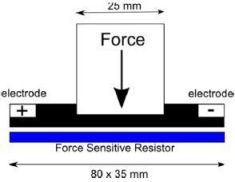
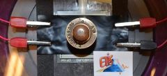 Figure 4 – Experimental assembly to measure the properties of the conductive rubber during the physical contact with the object
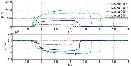 Figure 5 – Characteristics of the conductive film Velostat® when interacting with conductive object
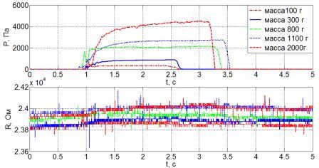 Figure 6 –Characteristics of the conductive film Velostat® when interacting with nonconductive object
Based on the results (Fig. 5, 6) it is possible to conclude that the conductive film Velostat® slightly reacts to the nonconductive objects. The tissue resistance varies negligibly, by 1.5 % when contacting with the nonconductive object but when contacting with the conductive object it varies by 30-50 %.
But this measurement was carried out taking into account the assumption that the complex Velostat® tissue impedance has purely active character. In the process of the investigation an assumption aroused that the tissue has some reactive resistance. To check this assumption a transient curve of the material in the non-load condition was taken. To do this a voltage surge with the amplitude 6.5 V was applied to one pair of electrodes and the tissue response was taken from the other pair (Fig. 7):
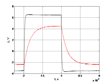 Figure 7 –The transient curve of the conductive film Velostat® in the non-load condition
Based on the results of this investigation it is possible to conclude that the conductive rubber Velostat® also has reactive resistance and Velostat® can be represented as the first-order factor with the response function:

with parameters:
- Т=1.3736 μs – integral time constant;
- k=0.6214 – link transfer factor.
Based on the experiment results it was concluded that for the artificial skin based on the conductive rubber Velostat® it is reasonable to use the alternating current with the frequency about:  . (The transient process stops at the time 5•Т, but for some allowance we used the alternating current with the period 10•Т).
Electrical impedance tomography (EIT)
This method permits to visualize the spatial distribution of the electrical impedance (or conductivity) inside the object based on the results of noninvasive electrical measurements. To reconstruct the image the meaning of the electrical potential is used which is measured on the object surface when the current is supplied through it. EIT is aimed at the reconstruction of the cross sectional image (2D, 3D) of the inner spatial distribution of electrical conductivity by introducing the small current values ( direct or alternating) with the help of electrodes located on the surface of the object under study and by measuring electrical potential [10]. EIT method is widely used in medicine, industry, natural and applied science. There are some measuring methods applied in EIT. The scientists Brown and Segar [11] proposed the method of neighbouring electrodes, and namely this method is used in the investigations in master's degree work. Figure 8 illustrates the application of this method for a cylindrical volume conductor with 16 equally spaced electrodes.
The current is first applied through the electrodes in pair 1-16, the current density between these electrodes is higher than among others. The current density decreases rapidly as a function of distance. Then the voltage difference between other electrodes pairs is measured which corresponds to 13 measurements to reconstruct the resistance. Next step is to supply the current through another electrode pair 2-1, and to measure successively 13 possible voltage drops. So for one skin image we receive 13•16 = 208 voltage measurements.
 Figure 8 – Method of neighbouring electrodes EIT for a cylindrical volume conductor with 16 equally spaced electrodes.
(animation : 7 frames, 10 repetitive cycles, 55 Kbyte)
Figure 8 – Method of neighbouring electrodes EIT for a cylindrical volume conductor with 16 equally spaced electrodes.
(animation : 7 frames, 10 repetitive cycles, 55 Kbyte)
There some other methods of EIT data collection. The cross method [12] does not have as good a sensitivity in the periphery as does the neighboring method, but has better sensitivity over the entire region. The opposite method of the impedance measurement gives more equal current distribution and has a good sensitivity. Besides there is an adaptive method [88], which suggests nonlinear dependence between the conductor size, the number of electrodes and the value of the applied current to receive the uniform current distribution.
In the further investigations the method of neighboring electrodes for data acquisition from the conductive tissue Velostat® will be used, and the process of data acquisition the EIT method will be used for image reconstruction. Another approach using artificial neural networks might be used for image reconstruction.
Conclusions
This master's degree work is devoted to the up-to – date scientific task in the sphere of robotics engineering - development of the tactile sensor to be used as artificial skin for an anthropomorphic robot. The following has been carried out so far:
The existing systems of tactile sensors possible to be applied as artificial skin have been analyzed.
The most suitable type of the tactile sensor, namely the conductive rubber has been chosen. The conductive tissue Velostat® has been selected as the conductive rubber.
A number of experiments to investigate the tissue Velostat® has been carried out.
The method of data collection from the conductive tissue and the image reconstruction of the pressure distribution on the surface of the conductive tissue has been analyzed and the method of neighbouring electrodes is the basis.
The following essential spheres will be investigated in the future:
The development and creation of the hardware part of the tactile sensor for the physical man – robot interaction.
The realization of the algorithms of the image reconstruction based on the artificial neural network application.
The estimation and experimental investigations or the developed artificial skin prototype.
Acknowledgment
The author wishes to greatly thank the people who have contributed to writing this work and carrying out investigations.
When the report is being written the master's degree work has not been finished yet. The terms of the work completion is January 2014. The more detailed information concerning this investigation can be obtained from the author and the work complete text and materials will be available after the master's degree work completion.
List of references
П.М. Таланчук, С. П. Голубков, В. П. Маслов. Сенсоры в контрольно-измерительной технике // Киев. Техника, C. 1991. – 173.
R.S. Dahiya, M.Valle. Tactile sensing for robotic applications.
Karsten Weiss, Heinz Woern. Tactile Sensor System for an Anthropomorphic Robotic Hand.
M. A. Diftler, R. Platt Jr, C. C. J., R. O. Ambrose, W. J. Bluethmann. Evolution of the nasa/darpa robonaut control system // IEEE Int. Conf. on Robotics and Automat., 2003‒P. 2543–2548.
Hyung-Kew Lee, Sun-Il Chang, and Euisik Yoon. A Flexible Polymer Tactile Sensor: Fabrication and Modular Expandability for Large Area Deployment // Journal of microelectromechanical systems, vol. 15, no. 6, december 2006.
Yoshiyuki Ohmura, Yasuo Kuniyoshi, Akihiko Nagakubo. Conformable and Scalable Tactile Sensor Skin for Curved Surfaces // Proceedings of the 2006 IEEE International Conference on Robotics and Automation Orlando, Florida - May 2006.
E. Torres-Jara, I. Vasilescu, R. Coral. A soft touch: Compliant tactile sensors for sensitive manipulation // CSAIL, Massachusetts Institute of Technology, Tech. Rep., 2006.
–ê. –ê. –ü—É–≥–∞—á. –£—Å–æ–≤–µ—Ä—à–µ–Ω—Å—Ç–≤–æ–≤–∞–Ω–∏–µ –∞–ª–≥–æ—Ä–∏—Ç–º–æ–≤ —É–ø—Ä–∞–≤–ª–µ–Ω–∏—è –¥–≤–∏–∂–µ–Ω–∏–µ–º —Å—Ñ–µ—Ä–æ–ø–æ–¥–æ–±–Ω—ã—Ö –æ–±—ä–µ–∫—Ç–æ–≤ –Ω–∞ –º–æ—Ç–æ—Ä–∏–∑–∏—Ä–æ–≤–∞–Ω–Ω–æ–π –ø–ª–æ—Å–∫–æ—Å—Ç–∏ —Å –ø–æ–º–æ—â—å—é —Ç–∞–∫—Ç–∏–ª—å–Ω–æ–π –æ–±—Ä–∞—Ç–Ω–æ–π —Å–≤—è–∑–∏ —Å –∏—Å–ø–æ–ª—å–∑–æ–≤–∞–Ω–∏–µ–º –∏—Å–∫—É—Å—Å—Ç–≤–µ–Ω–Ω–æ–π –∫–æ–∂–∏ –∏ –Ω–∞–¥–µ–∂–Ω–æ—Å—Ç—å –ø—Ä–µ–¥–ª–æ–∂–µ–Ω–Ω–æ–π —Ç–µ—Ö–Ω–∏—á–µ—Å–∫–æ–π —Å–∏—Å—Ç–µ–º—ã. –Ý—É–∫–æ–≤–æ–¥–∏—Ç–µ–ª–∏: –¥.—Ç.–Ω., –ø—Ä–æ—Ñ. –ö–æ–≤–∞–ª–µ–≤ –ê. –ü., –∫.—Ç.–Ω –ê–ª–µ–∫—Å–∞–Ω–¥—Ä –ü–∏—Ç—Ç–∏ (–£–Ω–∏–≤–µ—Ä—Å–∏—Ç–µ—Ç –°–µ—Ä–∂–∏-–ü–æ–Ω—Ç—É–∞–∑).
G. Pugach, V. Khomenko, A. Melnyk, A. Pitti, P. Henaff, P. Gaussier. Electronic hardware design of a low cost tactile sensor device for physical Human-Robot Interactions. IEEE ELNANO 2013 XXXIII International Scientific Conference Electronics and nanotechnology, - Kyiv, Ukraine : IEEE. – April 16-19, 2013. – pp. 445 – 448.
A. Adler, R. Guardo. Electrical impedance tomography: regularized imaging and contrast detection // Apr. 1996. IEEE Transactions on Medical Imaging, 15(2):170-179.
Brown B H, Seagar A. Applied potential tomography data collection problems // Int. Conf: on Electric and Phjsiol. Mras. 8 13-3 I.
Kauppinen P, Hyttinen J, Malmivuo J (2006): Sensitivity distribution visualizations of impedance tomography measurement strategies. Int. J. Bioelectromagnetism 8:(1) pp. VII/1 - VII/9.
Plug and Wear [˝ÎÂÍÚÓÌÌ˚È ÂÒÛÒ]. - –ÂÊËÏ ‰ÓÒÚÛÔý: www.plugandwear.com