
Abstract
Content
- Introduction
- 1. Reactance in power systems
- 1.1 Purpose of the reactors
- 1.2 Types of reactance
- 1.3 Device reactors
- 2.Mathematical modeling of reactors
- 2.1 The model for the effective values of voltage
- 2.2 The model for the instantaneous voltage
- 3. The effectiveness of the dual reactor in loss and voltage unbalance
- 3.1 The effectiveness of the dual reactor in symmetrical sinusoidal load
- 3.2 The effectiveness of the dual reactor at random loads
- Сonclusion
- References
Introduction
Reactance in networks is used to reduce short-circuit current, but normally created by Reactance voltage loss, which worsens the electromagnetic compatibility (EMC). The literature indicates that the twin reactors improve EMC, so the task of evaluating the effectiveness of the dual reactor (DR) is relevant for practice.
In the supervisor has been found that in some cases, the DR does not decrease, but increases the range of the effective values of voltage drops. However, in this study were not considered harmonics and unbalance. Evaluating the effectiveness of DR in these kinds of interference is relevant to science.
In this connection it is necessary to solve the following tasks:
The data will be used in the educational process. The results may be of interest to companies with electric arc furnaces, thyristor converters and other sources of EMC interference.
1 Reactance in power systems
1.1 Purpose of the reactors
The reactors are designed to limit short-circuit currents in electrical networks and maintain a certain level of voltage in the case of a short circuit in the power frequency of 50 Hz and 60 Hz. Reactors are used in circuits of power stations and substations, electrical parameters in accordance with passport figures [1]. Usage of reactors allows you to limit the rated breaking current line breakers and ensure thermal stability of the outgoing cables. Thanks to all undamaged reactor lines are live close to the nominal, which increases the reliability of the electrical installations and improves the conditions of electrical equipment.
1.2 Types of reactance
Perhaps individual (Figure 1.1), group reactance (Figure 1.2), dual reactor (Figure 1.3).
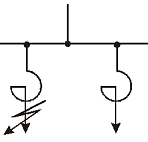
Figure 1.1 – Individual Reactance (IR)
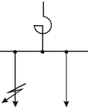
Figure 1.2 – Group Reactance (GR)
Figure 1.3 – Dual reactor
(DR)
(animation: 7 frames, 5 cycles of repeating, 10,5 kilobytes)
Reactor – a coreless coil. In normal mode, the resistance of the core xp – large, large voltage loss. If a short circuit due to saturation of the resistance falls, so short-circuit current limited and poorly may increase. When short-circuit xp two circuits, expressed in ohm - same. In normal mode, the group will create a large reactor voltage loss, as the reactor flows through the group sum of the currents, and through individual reactor – its only current. But the group reactor is cheaper than several individual reactors.
At DR two coils are located nearby. Depending on how the wire is wound, and how to turn on the reactor – the resistance of the windings can be different. Between the branches is the magnetic coupling, which is characterized by the magnetic coupling coefficient k. Typically, the coupling coefficient is 0.4–0.6. If the currents flowing in the branches in one direction – the resistance of each of the windings is reduced. That is, normally a small resistance.
If a short circuit when there is no feeding from the second branch, the resistance of the reactor increases as there is no magnetic coupling.
DR is the advantage that the voltage drop is less than a conventional reactor. Therefore, in the literature, it is recommended to reduce the voltage fluctuations [2]. But DR does not always reduce vibration. Taking into account the resistance of the network, there are areas in which DR reduces or increases the fluctuations in comparison with group or individual reactor – it all depends on the load of branches – they are dependent or not, the relationship is positive and negative. Therefore, the use of DR should be justified by calculation using the experimental record loads of branches.
One of the main parameters is the inductive reactance Xp, equal to the ratio of the voltage drop at the reactor UP to phase voltage Uf while flowing through it rated current. The inductive reactance is expressed as a percentage. If we neglect the ohmic resistance of the reactor, the
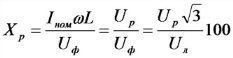
1.3 Device reactors
To maintain a constant current limiting inductance performed without iron cores. However, they obtained large size and weight. Reactors with iron cores with equal inductances would have smaller dimensions. However, they have high-current cores are saturated inductance of such reactors is sharply reduced and current limiting reactors are losing their properties at the very moment when they are needed. In view of this reactor with steel cores were not spread.
A proliferation of dual reactors. Such a reactor feeds the two feeders. The coils of each phase are included so that they create streams flow counter. If the nominal current inductance (and hence a voltage drop) of each of the coils is reduced because of the demagnetizing action other. With equal currents and coupling coefficient tends to unity, the inductance of the reactor would tend to zero. Reduced accordingly and the loss of voltage. If a short circuit on one of the feeders of the demagnetizing action of the coil of another feeder at rated current can be neglected. Inductance and current-limiting action of the dual reactor similarly obtained as a single.
For voltages up to 35 kV for indoor use almost exclusively widespread concrete reactors. Concrete reactor (Figure 1.4 a) is performed in the form of concentrically arranged turns one round of special insulated stranded wires, covered by a radially extending concrete column 2. Due to its flexibility wire damps the thermal and dynamic efforts and thereby partially relieves stress with concrete. The windings of the reactor at high currents are made of several parallel wires with a transposition of these parallels, which provides a uniform current distribution.
The number of columns is determined by the diameter of the winding. Basic insulation reactor – concrete, which takes a special process conditions and is available with high mechanical properties. The whole reactor is dried after manufacture, moisture resistant coating and impregnating varnishes. Each column reactor mounted on support insulators 3, which provide insulation from the ground, or between phases. The phases may be disposed vertically (Fig. 1.4, 6), and also horizontally or stepwise. All metal parts of the reactor are made of non-magnetic materials. At higher currents applied artificial cooling.
At voltages above 35 kV for outdoor use oil-water reactors (Figure 1.5). Winding 3 of the copper conductors, insulated cable paper, laid on the insulating cylinders 4 and placed in tanks (tank) 2, flooded with oil. The ends of windings of each phase are output via the bushings 1 to the outside. The oil serves as an insulating and cooling medium like. The alternating field coils of the reactor is closed through the wall of the tank, can cause excessive heating of the walls. To reduce the heating of the walls (and oil) becoming isolated to limit the flux through them. For this are the electromagnetic screens 5 or magnetic shunts [3]. The electromagnetic screen is a copper (alloy) shorted windings arranged concentrically with respect to the winding of the reactor vessel wall. Induced currents in the coils in the walls of the tank creates a field along the main counter, and it is almost entirely offset. Heating the walls is reduced. Magnetic shunt is a package of sheet steel, reinforced around the inside walls of the tank with his hand and create an artificial magnetic conductor with magnetic resistance, the resistance of the walls is much smaller tank. The magnetic flux reactor is closed by a magnetic shunt, and not through the walls.
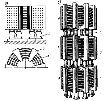
Figure 1.4 – General view of the concrete phase of the reactor (a) and the set of three-phase reactor (b)
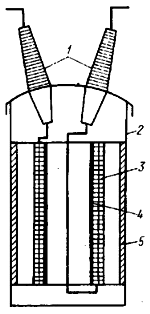
Figure 1.5 – A general view of an oil phase reactor
Limiting reactors are selected for rated current, voltage, resistance and inductance, check the thermal and short-circuit withstand the terms of the required level of bus voltage substation. Rated currents and inductive resistance of dual reactors are given in IEC 14794-79.
2. Mathematical modeling of reactors
2.1 The model for the effective values of voltage
Under the model is meant a mathematical description. For the sake of brevity, consider two groups of power consumers with electrical loads. The reactors and the network are considered as elements of a lumped: active rp and inductive xp resistance of the reactor, the resistance rc and inductance Lcof network. Voltage loss and asymmetry are determined by the current values of the direct UI and inverse UII sequence.
By the condition of short circuit current limiting resistance xp reactors are the same. In normal operation, the resistance of the left branch of the dual reactor through which current flows I1, reduced by the value of k•xp•I2/I1, determined by magnetic coupling coefficient k between the windings. In all schemes, the resistance network losses are equal to v3•X•(I1+I2). The uneven load distribution is characterized by irregularity factor βc = I2c/I1c. Denoting α = X/xp, Vc = v3•xp•I1c, we write the expression for the mean values of voltage drops in reference points for the three schemes (Fig. 2.1, 2.2, 2.3):
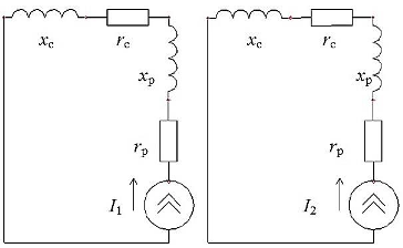
Figure 2.1 – A mathematical model of IR
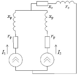
Figure 2.2 – A mathematical model of the GR
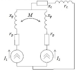
Figure 2.3 – A mathematical model of DR
2.2 The model for the instantaneous voltage
In the current section discusses the dynamic model of the DR, which allows the calculation of indicators on the specified EMC electric loads. In general, the starting point for the calculation are the processes of change in the instantaneous currents I1 and I2 branches DR (current curves). Before submission of the formulas recall the operator method of calculation.
The essence of the operator method is that at the first stage of the real time function i (t), u (t), called the originals are replaced with some new features I (p), U (p), called operator images. The correspondence between the original function f (t) and its operator image F (p) is set based on the direct conversion of the Laplace integral. For the original electrical circuit is a system of differential equations by the laws of Kirchhoff. Then each term in the equations are directly affected by the Laplace transform, and thus the system of differential equations is transformed into the corresponding system of operator equations. Circuit elements considered as a resistance Zi, the values of which we find the basis of the image transfer functions corresponding to the elements.
For example, a resistor:
For the inductance:
For containers:
The considered dynamic models calculate indicators EMC Wave
form at non-periodic non-linear loads. To estimate the variation of the
voltage unbalance and vibration processes are used  changes in the
effective values of voltage drops of each phase, which are moving
through the RMS averaging processes
changes in the
effective values of voltage drops of each phase, which are moving
through the RMS averaging processes  in the range of 0.02 sec.
3 The effectiveness of the dual reactor in loss and voltage unbalance
3.1 The effectiveness of the dual reactor in symmetrical sinusoidal load
This section discusses the effectiveness of the dual reactor in symmetrical sinusoidal load with equal amplitudes I1m = I2m = Im, but different phases ψ. Phase changes from –π to π [4]. For example, if one branch predominate induction motors, then ψ>0, and if synchronous, then ψ<0.
For DR currents of branches would be:
We assume that the system of infinite capacity (rc=0, Lc=0). Then, for the left branch:
Deviation of the phase voltage:
Amplitude:
For group reactance values are zero, ie DR is always worse than the GR.
For IR:
The amplitude does not depend on the phase of ψ:
It is planned to consider the more general case of different amplitudes I1m and I2m. The effectiveness will depend not only on the phase, but also on the αm= I1m/I2m. Likewise – at unbalance, but instead I1 – III.
3.2 The effectiveness of the dual reactor at random loads
For mains attached a large number of power consumers, so the total load I1(t) and I2(t) ) is a random process. These processes are characterized by average values I1c and I2c, standards σ1 and σ2, and the correlation coefficients.
First is comparable scheme with the individual reactance and
DR [5].
At low resistances network when α < k, with an
increase in βc zero negative voltage loss in the branch of DR
more compensates the loss of voltage. As a result, the total loss is
reduced and the efficiency of DR increases. Full compensation is
achieved when ![]() , where efficiency curves
tend to infinity. With further increase in the total loss of the
argument voltage changes sign, but as the assessment made by absolute
values, the effectiveness of DR decreases. Moreover, overcompensation
can become so large that the voltage drop exceeds the absolute value of
the voltage drop in the first circuit. According to the scope of the DR
at the average voltage deviation is determined by the inequality:
, where efficiency curves
tend to infinity. With further increase in the total loss of the
argument voltage changes sign, but as the assessment made by absolute
values, the effectiveness of DR decreases. Moreover, overcompensation
can become so large that the voltage drop exceeds the absolute value of
the voltage drop in the first circuit. According to the scope of the DR
at the average voltage deviation is determined by the inequality:
From which it follows that the restriction of applicability
will be only at  .
If (5) is not satisfied, the characteristic performance crosses the
x-axis, and then tends to a negative value
.
If (5) is not satisfied, the characteristic performance crosses the
x-axis, and then tends to a negative value . For large network resistances full payment is not
possible in the first scheme, and therefore the performance
characteristics have no gap, increase monotonically, tending to a
positive value
. For large network resistances full payment is not
possible in the first scheme, and therefore the performance
characteristics have no gap, increase monotonically, tending to a
positive value  .
.
We now turn to the circuit with a group reactor. This loss is
more than the value of the voltage ,so the efficiency of the DR is certainly higher.
With
,so the efficiency of the DR is certainly higher.
With  increasing
efficiency curves at first, but after the break point will not cross
the x-axis, tending to value
increasing
efficiency curves at first, but after the break point will not cross
the x-axis, tending to value 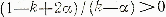 . At higher resistances network efficiency curves
are monotonically increasing, surpassing by value
. At higher resistances network efficiency curves
are monotonically increasing, surpassing by value  .
.
Consider the effectiveness of the DR by voltage fluctuations,
which are generally characterized by a dose of flicker. Quantitatively,
this dose is close to the variance of the process after the filter of
the dynamic model, which determines the rate. In this connection,
evaluation of the dose variations and similar dispersions. This allows
to assess the effectiveness of the dual reactance by CN as well as
within a range of voltage fluctuations, it is sufficient in the formula to substitute
values 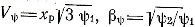 , where
ψ1, ψ2 dose load fluctuations.
, where
ψ1, ψ2 dose load fluctuations.
To determine the scope of DR by voltage fluctuations or dose range flicker for a uniform distribution must be substituted in (6) and (7) value βσ and decide inequality for α. As a result of the effectiveness of dual reactance compared with individual inequalities are:
–in the case of a positive correlation:
– uncorrelated and a negative correlation:
Similarly, we find that the DR group more effectively if
and the correlation coefficient is negative.
Conclusion
- Under the terms of reduction of short-circuit protection for all the schemes of inductive reactance in ohms resistance reactors should be the same.
- In mathematical models of reactors is necessary to consider their active resistance and inductance, and the DR – and even mutual inductance. In the equivalent circuits are presented load power sources.
- In the absence of interference depends on the effectiveness of DR shift angle between the currents of branches: there are areas of angles in which DR worsens EMC.
- . Effectiveness of DR in harmonics depends on the composition of harmonics in the branches and shear angles between them.
- To analyze the effectiveness of DR in casual loadings appropriate to use simulation methods of random loads of branches.
Writing this essay master's work was not completed. Final completion: December 2013. Full text of the and materials on the topic can be obtained from the author or his head after that date.
References
- Атабеков В.Б. Городские электрические сети. / В.Б. Атабеков , В.И. Крюков – М.: Стройиздат, 1987. – 384 с.
- Кузнецов В.Г., Куренный Э.Г., Лютый А.П. Электромагнитная совместимость. Несимметрия и несинусоидальность напряжения. – Донецк: Норд-пресс, 2005. – 250с.
- Варовей М.А. Автоматический регулятор для дугогосящего реактора / М. А. Варовей, А. А. Чупайленко ; М.А. Варовей, А.А. Чупайленко. – С.25-27.
- Куренный Э.Г. Оценка и нормирование несимметрии напряжений в системах электроснабжения общего назначения / Э. Г. Куренный [и др.] // Электричество. – 2008. – № 4. – С.18-26.
- Куренный Э.Г. Эффективность применения сдвоенных реакторов//Э.Г.Куренный, И.В.Пушная, Н.Н.Погребняк, Сулейман Халед, Л.Е.Клименко.—Техническая электродинамика, 1991, №3. – с.83-86.
- Справочник по проектированию электрических сетей и электрооборудования / Под ред. Ю. Г. Барыбина и др. – М.: Энергоатомиздат, 1991. – 464 с.
- ДСТУ 4194-1-3:2003. Трансформатори та реактори для перетворювачів з мережевою комутацією = Трансформаторы и реакторы для преобразователей с сетевой коммутацией. Частина 1-3 : Трансформатори та реактори для перетворювачів з мережевою комутацією. – Чинний від 2004-07-01. – К. : Держспоживстандарт України, 2004. – 13 с.