
Abstract
The Contents
- Introduction
- 1. The study asynchronous mode
- 2. Measures to improve the dynamic stability
- 3. Mathematical modeling of dynamic modes of synchronous generator
- Findings
- List of sources
Introduction
Providing dynamic stability of synchronous generators in emergency operation is one of the most pressing challenges of managing today's power plants and systems. The fact that the system maintains static stability in steady-state operation, yet allows us to state that it will be sustained and dramatic violations of the sudden it works like a short circuit, turn off the generators or lines, etc. [1].
When changing asynchronous generator with a decrease of the magnetic flux generated by this current in the rotor winding, the generator starts to consume reactive power from the network.
In asynchronous mode, the rotor winding induced voltage. If the winding is insulated or not included in electromachine agent, and rectifier excitation system eliminates the passage of current reverse polarity, the slides at high applied voltage can reach dangerous to the rotor windings and rectifiers value. Therefore, asynchronous mode is very dangerous for generators [3].
The aim is to study the asynchronous modes of power plants and the development of means to improve the dynamic stability.
The input data for the job are:
- Reference data of instantaneous values of currents, voltages, speeds turbine, etc. produced by the digital oscilloscope.
- Parameters of Power System (PS), which are calculated based on the equivalent E.M.F. E, the resistance R, capacitance C, inductance L [4].
The main objectives разработок и исследований:
- to prove the necessity of avoiding the asynchronous mode;
- identification of asynchronous modes at an early stage;
- improve discrete mathematical model to analyze the dynamic modes of the electrical system, a basis for a program PowerNet;
- propose a new principle of the protection of the asynchronous mode.
1. The study asynchronous mode
Consider the method of controlling the emission angle of the rotor. To do this, run the simulation excited asynchronous generator in the near short circuit [6].
Before considering the emergency mode determine the dependence of the stability of the emission angle of the rotor. While working at a (Fig. 1) and the turbine generator power balance each other. Assuming that the angle δa receives a small increase Δδ , a power generator, following a sinusoidal function of the angle also changes by a certain amount ΔР, wherein, as seen in Figure 1 at a positive angle increment Δδ also corresponds to a positive change in the generator power ΔР .
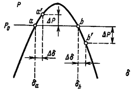
Figure 1 – Changing the angle increases power
As the turbine power, it does not depend on the angle δ and any changes of the last remains constant and equal Рo. As a result of changes in the balance of moments of turbine and generator is broken and the shaft of the machine occurs over time the nature of the brake as the braking torque of the generator due to the positive change in the power ΔР dominates the torque turbine.
Under the influence of the braking torque of the generator rotor starts to slow down, which causes the movement associated with the rotor emf vector generator downward angle δ. By decreasing the angle of the newly restored original operation mode at the point and, hence, this mode should be considered sustainable. The same conclusion can arrive at a negative angle increment Δδ at a.
A completely different picture is obtained at b. Here, a positive increase of the angle Δδ not accompanied by a positive and a negative change in the generator power δР. Changing the power generator causes excessive torque accelerating nature under the influence of which the angle is not reduced, but increases. As the angle of the generator power continues to fall, resulting in a further increase in the angle, etc. The process is accompanied by a continuous motion vector EMF voltage vector E with respect to the receiving system and the U station falls out of synchronism.
Figure 2 - Loss of synchronism
Thus, operation at the point b is statically unstable and impracticable.
Fig. 3 is a block diagram of thermal power plants. Simulated transient short-circuit on the side of the high-voltage (110 kV) and then removing it [5].
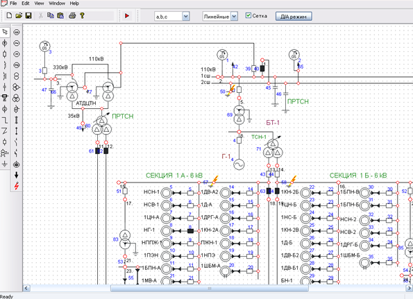
Figure 3 - Detail of the scheme EPP
See the process of disabling the short-circuit breaking time of 0.5 seconds.
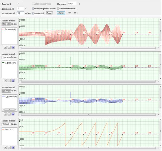
Figure 4 – Oscillogram transient fault clearance at 0.5 with a) current generator (branch number 4), and b) the voltage node number 8 c) the voltage of the node number 15, and d) the emission angle of the rotor.
Shows four waveforms. The first waveform shows the current branch number 4 (the generator), the second waveform voltage node number 8, the third waveform - the voltage at node 15, and the fourth waveform emission angle of the rotor Delta. During short fastening Delta grows and comes off after persistent agitated or asynchronous mode.
Figure 5 shows the transient short-circuit breaking through 0.25.
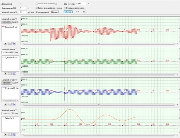
Figure – Oscillogram transient fault clearance at 0.25 seconds.
As can be seen from the waveform, the emission angle of the rotor during this time has no time exceed the critical value (90°), and after a short-circuit breaking is drawing generator into synchronism, accompanied by "vibrations" of the rotor.
2. Measures to improve the dynamic stability
Dynamic stability of the power system characterizes the ability of the system to maintain synchronism after the sudden and abrupt changes in the profile, or at accidents in the (short-circuit, frequent outages of generators, lines and transformers). After such a sudden disturbances in the normal operation of the system, a transient process, after which the newly established post-accident should occur operation [2].
There are several ways to improve the stability of:
- Generalized vector control changes the current based on its time differentiation.
- Monitoring frequency changes over time based on the solution of nonlinear systems of equations.
- On the corner of the vector diagram through the control of the resistance Z, calculated by the instantaneous values of the generalized current.
A detailed discussion of the generalized method of monitoring changes in the current vector based on its differentiation with respect to time with loved ones fault.
Enhancing the stability of the station for close damage is possible due to the use of new principles of microprocessor-based protection. This principle is to create a fast overcurrent protection, which performs analysis of the instantaneous values of the current vector of the generalized (GCV) and its first derivative with respect to time, since it is the derivative GCV significant difference in fault mode and swing.
The principle on the basis of the control values of the first derivative (GCV) can significantly increase the speed of protection than existing due to more accurate identification mode at early stage, since existing systems are generally responsive of the current values, which may lead to delay operation, during which emission angle of the rotor of the generator reaches a critical value.
3. Mathematical modeling of dynamic modes of synchronous generator
Computer simulation of emergency operation involving the violation of the dynamic stability.
The calculation of the instantaneous values of current, voltage and electromechanical units in the transition process is completed using PowerNet, developed on the basis of discrete mathematical models [8].
Consider the case of an asynchronous course.
Design scheme is based on a block 200 MW. Generator is equipped with a system of self-excitation thyristor with ARZ proportional action and forcing. Autotransformer connection is disabled [9].
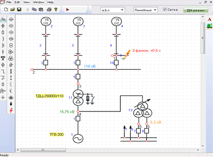
Figure 6 - Design model 200 MW unit for the analysis of asynchronous
We analyze the following modes:
- 0 sec. – normal mode;
- 0,5 sec. – the occurrence of a 3-phase short-circuit on the tires of a 110 kV;
- 1,0 sec. – shutdown fault protection relay.
Figure 7 shows the transient waveforms obtained through simulation. At the 1st graph – current generator, at 2 – terminal voltage of the generator (phase A), at 3-м – shaft torque generator, on the ground – relative angular velocity of the turbine.
The size of the shock-circuit current in this mode – 80 кА. After one frame from the beginning of damage has been disconnected and then went swing rotor (shown in Figure 3), and further, came out of synchronism with the generator system. This mode is accompanied by the beating of current with a large enough amplitude (up to 70 kA).
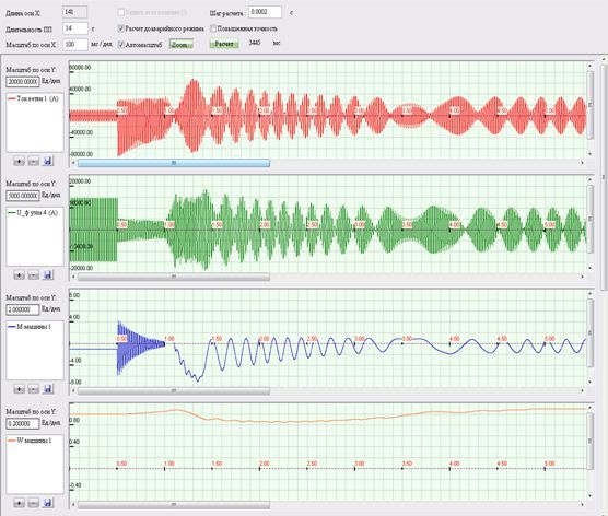
Figure 7 - Calculation of-step waveform generator circuit breaking through in 0.5 seconds (the time scale of 100 ms / div)
Perform the analysis of the behavior of the generator using fast protection based on measurements of instantaneous values GCV and its derivative, a short circuit to disable 0.1.
GCV found as:
where ia, ib ,ic – respectively currents in the phases A, B, C [7].
Further it is necessary find its first derivative with respect to time by numerical differentiation.
The derivative of the thrust vectoring mode fault is a significant change, and the power swing - no, because this defense will respond only to short-circuit.
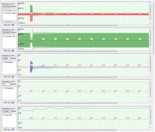
Figure 8 - Estimated recovery waveform generator during normal circuit breaking speed protection (scale is 100 ms / div)
Fig. 8 (Figure 1) can see the variation of the stator current and OVT (envelope curve) in normal mode, short-circuit, and the pull-in generator in synchronism. According to Figure 4 shows that during the course of short-circuit current mechanical state of the turbine (speed) changed slightly. Defence responded to the sharp increase in GCV.
Then, after some hesitation (the emission angle of the rotor on the chart 5), there was a restoration of synchronous mode with the issuance of the network nominal active power (Figure 3, the torque is equal to 1).
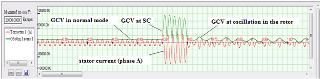
Figure 9 - Estimated recovery waveform generator during normal circuit breaking speed protection (scale 20 ms / div)
Figure 9 shows stator current waveforms and GCV larger scale. On these curves show a significant difference in the rate of change of mode, short-circuit and power swing, while the instantaneous values of current and short-circuit currents may differ slightly from the current synchronization. With this protection, reacting to the time derivative does not require additional tuning away from large current power swing, which increases its sensitivity [10].
Findings
The paper discusses the general provisions on dynamic stability of power systems. These three methods of increasing dynamic stability, one of which is thoroughly discussed.
Proposed a new principle of the protection of loved ones fault, based on control of the speed of change (first derivative) of the generalized current vector. As today's current protection, tend to react to the increase in the effective value of the fault current to ensure that the selectivity of their action is necessary to significantly reduce the speed of defenses. Poor performance in some cases can disrupt the dynamic stability of the system, in particular asynchronously. Therefore, a high-speed overcurrent protection on the basis of the analysis of the instantaneous values of GCV and its first derivative is a promising today. In order to prove this, it was mathematically modeled close to the terminals of the generator short circuit in the program PowerNet.
Also in this work:
- With the help of mathematical modeling of transient faults at close was investigated asynchronous generator, we have proved the necessity of avoiding this mode.
- We prove that in some cases may cause the sustainable pole slipping even with the correct operation of all safety devices and automation.
- Advanced discrete mathematical model to analyze the dynamic modes of the electrical system, a basis for a program of PowerNet.
In writing this essay master's work is not yet complete. Final completion: December 2013. Full text of the work and materials on the topic can be obtained from the author or his manager after that date.
List of sources
- Андерсон П. Управление энергосистемами и устойчивость / Андерсон П., Фуад А.; пер. с англ. под ред. Я.Н. Лугинского. - М.: Энергия, 1980. - 568 с.
- Устойчивость энергосистемы. Общие сведения. Способы повышения устойчивости [Электронный ресурс]. – Режим доступа: http://electric-zone.ru/ustojchivost-energosistemy....
- Эксплуатация генераторов и синхронных компенсаторов [Электронный ресурс]. – Режим доступа: www.motor-remont.ru/books....
- Гамм Б.З. Исследование переходных процессов в электроэнергетической системе при учете некоторых ее элементов динамическими характеристиками / Б.З. Гамм / / Труды СибНИИЭ. - 1972. - Вып.21. - С.43-48.
- Заболотный И.П. Математическая модель для расчет динамических режимов электрической системы / И.П. Заболотный, С.А. Гришанов / / Вестник Восточноукраинского национального университета. - М.: ВНУ. - 2001. - № 3 (37). - С. 79 - 85.
- Гуревич Ю.Е. Расчеты устойчивости и противоаварийной автоматики в энергосистемам / Гуревич Ю.Е., Либова Л.Е., окинешь А.А. - М.: Энергоатомиздат, 1990. - 390 с.
- Рогозин Г.Г. Программа расчета токов трехфазных короткого замыкания в сложной электрической системе с внедрением принципов функционального моделирования / Г.Г. Рогозин, А.Ю. Коваль / / Моделирование и расчет на ЦВМ режимов энергетических систем. - М.: Наук.думка. - 1977. - С.11-20.
- Сивокобыленко В.Ф. Математическое моделирование электромеханических переходных процессов на электрических станциях / В.Ф. Сивокобыленко, М.А. Меженкова / / журнал «Электричество». - 2001. - № 4. - С.5-9.
- Сивокобыленко В.Ф. Определение параметров эквивалентных схем замещения турбогенераторов для расчетов на математических моделях / В.Ф. Сивокобыленко, М.А. Меженкова / / Сб. наук.працьДонДТУ.Серия «Электротехника и энергетика». -Донецк: ДонГТУ. - 2000. - Вып. 17. - С. 38- 41.
- Авраменко В.Н. Моделирование электроэнергетических систем - достижения и перспективы научных исследований / В.Н. Авраменко / / Техническая электродинамика. - 1997. - № 1. - С.73-80.