
Abstract
This master's work is not completed yet. Final completion: January 2014. Full text of the work and materials on the topic can be obtained from the author or his adviser after that date.
CONTENTS
- Introduction
- 1. Actuality
- 2. The purpose and objectives of the study
- 3. The classification of thin-walled parts
- 4. The study features of the use of ultrasound for the machining of thin-walled cylindrical products
- 5. Engineering design
- Conclusion
- References
INTRODUCTION
At present, more and more attention paid to the development and improvement of the treatment of products with the removal of relatively small metal layers and creating on the surface and in the surface layer of the necessary physical and mechanical properties and surface roughness.
The constant development of the technology at the current stage requires the use of products that have thin walls (in order to save material and to facilitate the design as a whole). Now their number has increased in the total mass of parts subjected to mechanical processing. Thin-walled tube and shell structure as providing a high assembly density, are widely used in a variety of industries and, most importantly, in the responsible areas: oil, aircraft and rocket construction, cryogenic and refrigeration systems, space and military - industrial developments.
Solving the problem of reducing the amount of metal products has led to appearance numbers of the parts included in these products, which are characterized as non-rigid, one of the main groups contains thin-walled cylindrical parts.
In world practice, developed a large number of metal processing methods. By their nature they are complicated. The intensity of the processes of destruction, deformation, the transformation of the parts has increased significantly. In the development and improvement of methods of processing, the tendency of simultaneous exposure to workpieces and parts of mechanical loads and chemicals, thermals, or magnetic fields, electric and radiant energy, the energy of elementary particles, etc. in a their different combinations.
Experience has shown that there are no universal methods for processing of various structural materials, as each has its own specific features of rational application. Engineers and constructors have to choose a highly effective method of processing from large number of possible or or create them on the basis of the combined method of manufacturing parts.
Currently, all major branches of engineering in large-scale use of combined methods of materials processing. These techniques are developing rapidly, not only because of its relative youth, having availability ideas and opportunities, universality of energy used, but mainly due to the development of modern engineering.
1. ACTUALITY
In the process of cutting a workpiece and the cutting edge of the tool make the elastic vibrations. Therefore, to achieve high precision processing is necessary not only to carry out a static analysis of the relative position of the workpiece and the tool (which directly affects the machining accuracy), but also a certain degree of vibrational analysis system machine-tool tool-workpiece dynamically, ie during oscillations.
If in addition to the cutting force, which varies with high frequency sinusoidal, there is another component that is close by its frequency to the natural frequency of the tool or the workpiece, the vibrations may occur that reduce accuracy. This may create a situation that the processing will not be possible at all. In conventional processing of cutting is assumed that almost all oscillatory phenomena are undesirable. All textbooks indicated that it is necessary to use such cutting conditions under which no oscillations occur. This attention to the fact that the processing items should be in the low-frequency oscillation region where the amplitude is large enough and there may be noticeable jitter workpiece and the tool. However, for a long time to carry out processing recommendations given superimposed high frequency vibrations, in particular ultrasonic.
In a study of this relatively new method of processing has been found that it is one of the promising methods of processing of the future, and this was associated with its features:
- significant reduction of cutting forces in the processing;
- remedy node;
- providing access lubricants cooling of process fluids in the cutting zone;
- reducing the height of the surface asperities processed several times;
- minimizing or absence of residual stresses on the treated surface after the application of ultrasonic technology;
- decline contact friction.
Simultaneously with the increase in the number of thin-walled tubes and increased requirements for precision surfaces sizes, shapes, and their mutual arrangement. In the precision engineering tolerances on the order of micrometers. Known solutions to obtain pipes by plastic deformation. For high-precision cylindrical products used successfully rolling. But rolling of hole complex configuration as the design complexity that entails a complicated manufacturing technology sheeting, its increased cost and reduced reliability. Becomes the question of the feasibility using of rolling, and have to resort to cutting. Cutting by their nature less productive than the plastic deformation, as shaping occurs not in the the logging volumes, and on its surface. In the machining process of forming geometrically possible accuracy is reduced due to technological manifestation of heredity and the actual errors of turning. Practice shows that the intensification of the cutting is usually worse accuracy, gives rise to strong vibration.
Therefore, the development of ways and means to ensure the specified accuracy of the output parameters of thin-walled cylindrical products and reducing the complexity of their manufacture is an actual scientific problem.
2. THE PURPOSE AND OBJECTIVES OF THE STUDY
The purpose of this work is to improve the quality of engineering products based on special composite technology through the development of a common approach their creation, based on the composition of the synthesis of various features of technology options, in which the number of ways of increasing the quality of the products is determined by the number of choices of technologies that make up the composite technology.
To achieve this purpose in the Master's work following were set the next objectives:
- Creating a universal laboratory bench for studying the mechanisms of ultrasonic influence from different directions on the cutting process. The definition of positive and negative factors of the application of ultrasonic processing. Identification of factors that can positively influence of the ultrasonic processing;
- Investigation of influence of ultrasonic processing on the quality of the surface and the surface layer on the formation of metal residues;
- Investigation of dynamic characteristics of an elastic system ultrasonic unit;
- Investigation of influence of ultrasonic influence on the life of the tool to study the nature of this influence, identifying ways to increase tool life by ultrasonic influence on the process of cutting;
- Rational selection of processing conditions in order to minimize residual strains thin-walled products;
- Determining the ability of the deforming process of residual stress in the processing of thin-walled cylindrical products tocheniem complex surface shape in order to manage their residual strains.
3. THE CLASSIFICATION OF THIN-WALLED PARTS
To carry out the synthesis process must be a certain database from which need make the necessary choices possible solutions or solutions obtained relate to a class of objects. With all the content of the database must be subject to certain laws, and the location of processing facilities should be carried out according to some laws. This problem is solved by the thin-walled parts classification.
In the design process to identify common properties of objects helps you to find general principles that lead to a simpler design technology of thin-walled parts. To date, have not been developed rigorous methods of classification and there are no general rules that allow to allocate classes and objects. However, classifying, we combine into one group objects that have the same structure and behavior. A reasonable classification is undoubtedly part of any exact science [1,5].
The classification of thin-walled parts much easier to understand the main issues and the further development of a common theoretical approach synthesis process combined processing of thin-walled products. The classification helps to define a generalized, specialized and a collective hierarchy of objects and classes. The purpose classification is to find common properties of objects and their behavior [1,6].
Figure 3.1 shows the classification of the products with thin surfaces. The classification is performed in the following ways:
- by the form product;
- by the rigidity of the product;
- by appointment;
- by wall thickness articles;
- by the type of internal cavities;
- by the form of operational functions;
- by the quality of the surface layer;
- by the methods of processing;
- by the degree of precision.
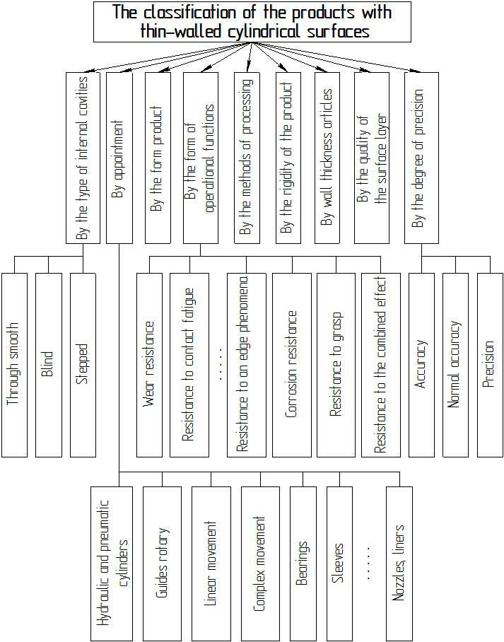
Figure 3.1 – The classification of the products with thin-walled cylindrical surfaces
By the form product, the products with thin-walled cylindrical surfaces are classified as follows: sleeve and cups, discs and rings, cylinders and tubes [1,7].
For disks and rings include such products in which the ratio of height to diameter D N does not exceed the value of Н/D≤0,5. As for the ratio of the outer D ring to the inner diameter d must not exceed the following values of D/d≤2,0. For cups and sleeves ratio of height to diameter is within the following range of 0,5 < Н/D ≤ 2,0. Cylinders and tubes have a height to diameter ratio which is greater than the value of Н/D > 2,0.
By the rigidity of the product, products with cylindrical surfaces are divided into the following: rigid and nonrigid, normal stiffness.
Rigid products - by the deformation which does not affect the forces in securing devices in the processing. Normal stiffness - which deformation of fixing in the processing device is within the tolerance of processing. For non-rigid products require special adaptations for a given rigidity, as without these devices may deform the product in excess of accuracy to processing.
By the width of the wall surfaces of the cylindrical articles are divided into products having a wall thickness: 0,3 … 1,0 mm; 1,0 … 3,0 mm; 3,0 … 10,0 mm.
By type of internal cavities, thin-walled cylindrical products are divided into the following: through smooth, blind and stepped.
According to the degree of precision, thin-walled cylindrical surfaces can be: low accuracy, normal accuracy, precision.
By appointment, thin-walled cylindrical surfaces can be subdivided into: guides rotary, linear and complex movements, hydraulic and pneumatic cylinders, bearings, sleeves, nozzles, liners, etc.
By appearance operational functions performed, thin cylindrical surface may implement the following functions: resistance to contact fatigue, wear resistance, resistance to an edge phenomena, corrosion resistance, resistance to grasp, resistance to the combined effect, etc.
4. THE STUDY FEATURES OF THE USE OF ULTRASOUND FOR THE MACHINING OF THIN-WALLED CYLINDRICAL PRODUCTS
Constructions machines destined for mechanical processing, can not allow small variations of the workpiece and the tool, which form a kind of oscillating system. A common case is a superimposed vibration cutting in which the cutting forces act in the form of pulses, and heat is negligible. Usually the cutting processing, which is accompanied by the release of heat and due to the effect of cutting forces, consisting of static force and imposed on it a variable component (varying sinusoidal) is a special case. These circumstances must be taken into account when considering the principles of precision machining.
The vibrating cutting process involves the use of special equipment that needs to be handled adroitly, that creates some difficulties. However, after appropriate adjustment of such equipment in the future will not specifically require highly qualified personnel. In this case, even when only low-skilled workers can establish continuous production of parts having a small size distribution and practically constant precision. The vibrating cutting process enables implement precise handling, using only turning. It is possible to accurately handle even the materials that are used to obtain the required accuracy is always subjected to grinding. The works, which were carried out before, such as the expensive grinders (cylindrical grinding, surface grinding, intragrinding, etc.), and vibration cutting are unnecessary. Thus, a vibration cutting has a number of advantages, which can reduce the volume of work and material costs.
The special features of the use of ultrasound in the machining of thin-walled cylindrical products include:
- reducing cutting resistance;
- increase the accuracy of process;
- cutting room temperature;
- exclusion of the node;
- if such processing is not formed and no plastic deformation occur burrs;
- roughness of the resulting surface is determined only by geometrical factors;
- shaving goes smoothly;
- improved lubricating and cooling effect of cooling lubricant technology environment;
- the distance between the surface of the resulting micro-asperities are more satisfactory;
- surface may iris;
- increased resistance to wear;
- increases corrosion resistance;
- increased tools resistance.
All of these benefits in one way or another can be realized with a vibrating cutting process. Consider the effect of each of these in more detail. The subject of discussion is the oscillatory system, which has a low natural frequency, which is acted on impulse cutting forces. It should be noted that the period of the force and the duration thereof is very small. In the study measured the pulse of cutting force, which is averaged and gives the average cutting force. For measurements using the experimental setup, where the cutting force is determined by the deformation of the elastic element that the glued strain gauges. It can be assumed that the vibration cutting the absolute value of the instantaneous cutting forces or pulsed cutting forces should decrease. The average cutting force is 3-10 times less than developed during normal cutting process.
When the vibration cutting, when the forces are pulsed in the case of the skillful use of the transition region of dynamic characteristics of the machine vibrating system can not create an environment in which the elastic vibrations as if suspended and movement become static, and the average cutting force is reduced.
Improving machining accuracy with a vibrating cutting takes place due to fluctuations in the cutting edge of the tool. Thus during the time the cutting edge is in contact with the workpiece and the shavings produced. We can assume that during this time the position of the cutting edge (top cutter) during the cutting process remains the same. Fluctuations in the workpiece, too, as would be terminated. This improves accuracy. Even with the use of cutting with vibrations in mass production size distribution produced parts is significantly reduced. Selective inspection showed that even at small depths of cut (a few micrometers) accuracy remains at the desired level for a long time.
In impulse force is applied to the pulse shape and the heat released during the cutting process. In this regard, cutting vibration differs from the usual. When the vibration cutting the average cutting force is dramatically reduced. In turn, the average temperature of the cutting also substantially reduced (approximately to ambient). Thus on the shavings do not appear discoloration that occurs during normal cutting due to oxidation. Shavings formed after cutting vibration can, without fear of getting burned, taking with his bare hands, in the ordinary cutting in general is unthinkable.
Average cuts can be compared to soldering, in which the heated soldering iron hard pressed to detail. In contrast, when the vibration cutting heating occurs only as a result of constant rapid movements up and down the soldering iron; wherein solder never be able to finish. In conventional cutting essential problem is growing temperature. Under the influence of this temperature may be thermal deformation of the workpiece, which degrades accuracy. Meanwhile, in the case of vibration cutting set temperature in most cases reduces accuracy.
Exclusion of the node. When vibration cutting processing does not occur vibration temperature rise shavings formed in the oscillating system instability tool - workpiece during the transient. Therefore, even if we assume that there are some factors that promote the occurrence of built-up edge on the cutting edge of the tool, in view of the short duration of the interaction of setting the node to the cutting edge does not occur.
This way you can perform precision cutting of thin-walled products, which are usually was treated before grinding, vibrating diamond tool can cut hardened steel. It is hoped that in the future instead of grinding machines for processing (sharpening) of the tool will be used machines with vibrating cutting tool. On the basis of the principle of cutting vibration can create a very diverse new machining equipment [3].
5. ENGINEERING DESIGN
In the field of ultrasonic frequencies generated by magnetostrictive vibrators, vibrating exercise processing without creating a hub proper design and selection of a suitable tool geometry is virtually impossible.
For oscillatory systems a cutting tool with magnetostrictive vibrators requires the following:
- when the tool is mounted on the hub used to increase the amplitude of fluctuations, it is necessary to achieve a resonance frequency of the vibrator and the tool;
- cutting tool should be easily fixed to a vibrator or a hub and is easily removed from them;
- for the oscillatory system tool should identify the coordinates of the vibrations and attach to a support tool in these places;
- if the oscillating system is connected with a support tool in the vibration nodes on the bolts, you need to pick up such structures, in which the natural frequency of the system is not changed [3].
Simple geometric considerations show that the oscillations of the top of the cutter at an angle to the direction of motion will degrade accuracy, ie fluctuations will be harmful. Therefore, there are three methods for applying fluctuations tool:
- in the direction of the axial component of the cutting force;
- in the radial direction;
- in the direction of the main component of the cutting force.
Given the superposition of oscillations in different directions were designed apparatus, for applying high frequency vibrations to the tool in the radial and tangential directions that shows its versatility. The plant, which is shown in Figure 5.1, was designed in the pre-CAD system SolidWorks and committed only variations in the radial direction.
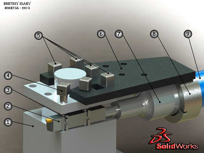
Figure 5.1 - Apparatus for radial direction of the oscillation
(1- the tool holder; 2 – cutter ; 3 – the guide supports; 4 – screws М14; 5 – screws М14(shortened); 6 – steel sheet; 7 – hub stepped; 8 – ring; 9 – the magnetostrictive transducer)
The apparstus consists of a stepped hub 7 to which the cutter 2 is attached via a pin. In the ring 8 is welded to the sheet 6 is mounted on the outer thread of the magnetostrictive transducer 9. A cutter with hub mounted on the internal thread to the transducer. The assembly is mounted on the tool holder of machine tool 1 and fixed with screws 5. According to earlier calculations, the tool is installed in the operating position between the guide mainstays 3 and is urged screws 4.
Experiments are planned on the basis of screw-cutting lathe 1M61 model [8]. For a given size machine is designed apparatus, an example of work which is shown in Figure 5.2.
Figure 5.2 - Animated examples of the apparatus for radial superposition of vibrations, designed in SolidWorks(8 image's,22 frames/sec, volume - 507kb)
It is known that the application of high-frequency oscillations in the tangential tool - a perspective direction of research, therefore envisage retuning apparatus, as shown in Figure 5.3, to ensure the tangential vibrations.
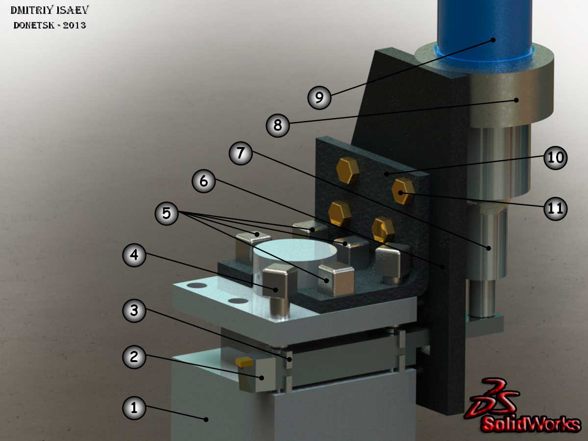
Figure 5.3 - Apparatus for tangential direction of oscillation
(1- the tool holder; 2 – cutter; 3 – the guide supports; 4 – screws М14; 5 – screws М14(shortened); 6 – steel sheet; 7 – hub stepped; 8 – ring; 9 – the magnetostrictive transducer; 10 – steel angle; 11 – screws М12)
УThe unit consists of a magnetostrictive transducer 9, rings 8, a stepped hub 7 and steel sheet 6 set vertically and we fix with screws 11 to a steel angle 10 which fixed to the toolholder 1 with screws 5. The cutter 2 having an elongated shank portion is set in the working position and are fixed with screws 4. The cutter fixed to a hub via a pin.
Then transducer connected to an ultrasonic generator (in this case - Model UZG1-1), which will convert electric energy at industrial frequency electrical energy of ultrasonic frequency [9]. Since the transducer is heated during operation - the coolant supply is provided an electric pump of the machine to drive the nozzles at the rear of the housing.
CONCLUSION
This work the analysis the current state of the question of vibration cutting thin-walled products. Thus it is possible to carry out precise cutting of thin-walled products, which are usually processed before grinding, vibrating diamond tool can cut hardened steel. It is hoped that in the future instead of grinding machines for processing (sharpening) of the tool will be used machines with vibrating cutting tool. On the basis of the principle of cutting vibration can create a very varied new machining equipment.
Combined processing method, namely the use of ultrasonic vibrations in the process of turning thin-walled products require further investigation as to the use of ultrasound, results in a marked reduction in cutting force, which in turn significantly reduces elastic squeezing in the system of MTAP(Machine tool attachment part), reducing roughness, and improvement of corrosion and wear resistance, increased accuracy, and a significant reduction in wear of machine.
This master's work is not completed yet. Final completion: January 2014. Full text of the work and materials on the topic can be obtained from the author or his adviser after that date.
REFERENCES
- Таровик А.Б., Михайлов А.Н. Классификация и особенности эксплуатации изделий с тонкостенными цилиндрическими поверхностями // Cб. трудов межд. науч.-тех. конф. в г. Севастополе 17 – 22 сентября 2012 г. – Донецк: ДонНТУ, 2012.
- Таровик А.Б., Михайлов А.Н. Классификация комбинированных методов обработки тонкостенных цилиндрических изделий // Прогресивні технології і системи машинобудування: Міжнародний зб. наукових праць. - Донецьк: ДонНТУ, 2012.
- Кумабэ Д. Вибрационное резание: Пер. с яп. С.Л. Масленникова/ Под ред. И.И. Портнова, В.В. Белова. – М.: Машиностроение, 1985. – 424 с.
- Астахов С.А. Высокопроизводительное точение тонкостенных закалённых цилиндрических заготовок // Автореферат диссертации по машиностроению и машиноведению. - Тула:ТулГУ, 2012.
- Хубка В. Теория технических систем: Пер. с нем. – М.: Мир, 1987. – 208 с.
- Михайлов А.Н. Основы синтеза функционально-ориентированных технологий машиностроения. – Донецк: ДонНТУ, 2008. – 346 с.
- Кривошапко С.Н. Аналитические поверхности в архитектуре зданий, конструкций и изделий. – М.: Либроком, 2012. – 328 с.
- Станок токарно-винторезный модели 1М61. Руководство по эксплуатации. - М:Машиностроение, 1981.
- Генератор ультразвуковой модели УЗГ1-1. Руководство по эксплуатации. - М:МашГиз, 1985.