
Summary on the theme of master's work
Content
- Introduction
- 1. Relevance of the topic
- 2. Goal
- 3. The main objectives
- 4. Review of existing methods
- 5. Dock design automation systems
- 5.1 The rationale for the direction of solving the problem
- 5.2 The development of the automatic adjustment of the liquid level
- 5.3 The development of the automatic adjustment of the coolant temperature
- 5.4 The development of the automatic adjustment of stiffness coolant
- 5.5 Development of structural and functional circuits
- Overview of results and conclusions
- List of sources
Introduction
Automated production is a process of transfer functions of control and production management from the man with an automatic device.
When creating automated systems should take into account the level of technology and equipment, the state of organization and management. You can not only reduce production automation to the automation of control if the basic processes and equipment remain at the same level.
Depending on the degree of automation of management functions are distinguished: manual, automatic and automatic operation. When manually managing all functions of the process performs a human operator. In the automatic control of the functions a person takes, and the other part - automatic device. In automatic mode all functions are performed by automatic devices.
1. Relevance of the topic
The cooling system in a steel plant is a very important part of the production process. Therefore, optimization and improvement in the performance of her work has a positive impact on energy consumption and the production process as a whole.
In the water-cooling system to monitor the level of coolant and its temperature in the tank to prevent it falling off, as it leads to a deterioration of the cooling elements of production, which may adversely affect the quality of products. Also important is the control of stiffness coolant (water) to increase the life of the cooling system elements. High stiffness implies copious water salt deposits in the cooling elements of the system, which entails the reduction of overall system performance, excessive wear and the individual elements leads to a probability of interruption due to the node and stopping the maintenance of the production line. This leads to significant losses.[1].
Need constant monitoring and control of these parameters, which in the future will extend the life of the equipment. Also allows full automation of the process to achieve stability of the system parameters and minimize the amount of deposits and wear on equipment.
2. Goal
The purpose of development - improving quality indicators of industrial cooling elements on the rolling mills, namely, maintaining the accuracy of the possible modes, reliability, automation components, reduce energy consumption for cooling by means of the development of the automation system of the object.
3. The main objectives
- Ensure effective monitoring and control of temperature, level and composition of the coolant in order to improve the reliability and quality of cooling.
- Provide automatic control and stabilization of the temperature of the liquid.
- Take control of the equipment to prevent accidents.
- Uninterrupted power supply automation system.
4. Review of existing methods
At this point in Donetsk metal factory applied this scheme (Figure 2.1), the control and regulation of fluid in the cooling system. This scheme has a number of drawbacks.
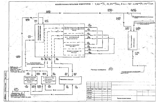 |
Figure 4.1 — Carrying water supply scheme DMPZ
This arrangement allows the initial softening water before feeding into the cooling system maintains a constant water level in the tank, coolant supply furnaces, and its subsequent cooling. However, very significant drawback of this scheme is that the cooling fluid and maintaining its temperature at the expense of constant circulation of water through the cooling tower. In this case, there is a need to use a cooling tower with obviously greater cooling capacity than is necessary to create a reserve in case of need and subject to weather conditions. This scheme does not provide tracking coolant temperature, which may lead to deterioration of cooling sharp increase heat furnace and, consequently, increase the coolant temperature[2].
Also in this scheme the compounds of reducing the concentration of metal impurities is carried out in water by compensating for losses of liquid softened water. Such a scheme can not maintain acceptable levels of impurities, which leads to increased fouling of pipes, water tanks, failure of the pumps and other related problems. Replacing the water softer is manual blowdown tank softened water.
Regarded circuit has many drawbacks and requires considerable improvement and doproektirovaniya to improve cooling, reliability, increased operating life and reduce influence of the human factor in the stability of the whole system.
To solve these problems is possible to use the following scheme developed for JSC "Severstal HARDWARE"[3]:
The implementation of the cascade scheme of pumping units, maintenance of automatic three process parameters: pressure, temperature and level of cooling water needed to provide water cycle cooling system rolling and drawing mills, power energy equipment (thyristor control units), and the resulting product rolling mills .
The Russian company "HMT service" offered conceptual engineering solutions to reduce energy costs and reduce staff duty shift through the introduction of programmable control systems and coordination of electric pumps in a cascade configuration of two autonomous pumping stations.
Automated control system for cooling metal-working equipment, the proposed plant "Severstal HARDWARE", includes:
- eight-channel PID controllers OWEN TRM148;
- meter-controller with RS-485 OWEN TRM202;
- ARIES PD100 pressure sensors;
- temperature sensors and TPA accident;
- hydrostatic level sensors.
The basis of the automated control systems are devices OWEN. The choice of this product was made for several reasons. The first and most important - is that the domestic manufacturer OWEN produces high-tech products, proven many times in different systems, ranging from simple to complex rapredelitelnymi systems.
In this project universal PID TRM148 allows processing in software logical field and multiscale eight independent signals from different sensors, and then output to any of the eight output channels as an analog current signal or a "dry contact". These features allow the chain to realize proportional control output and alarm circuit warning of lower and upper limits of controlled parameters. We regulator convenient man-machine interface with a Russian configurator settings can be changed directly on the keypad unit. The thermostat has a colorful light display with a well recognizable figures that allows service personnel to observe the stress-free process parameters from a distance. If necessary, it is possible to integrate the device into a single scheduling system via the integrated RS-485 interface.
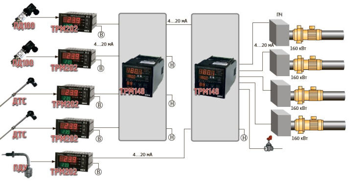 |
Figure 4.2— Functional diagram of the control pump units of the Cold
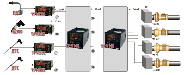 |
Figure 4.3 — Functional diagram of the control pump units a hot group
First feeding station with five pumping units Cold Group 160 kW each provides automatic inflow of water required in the steel-rolling mill. Automation based on regulators TRM148 TRM202 and maintains the desired temperature of metal settings, including forceful power equipment, as well as most of the products. At the same time automatically controlled by the loss of water in the working cycle, which is consumed by evaporation in the cooling towers. TRM148 valve regulates feeding position and sets the predetermined water level in the intermediate tank.
The second station with five pumping units hot band from 93 kW each works without attendants. Independent automatic second pumping station provides recycled water after cooling equipment. The heated coolant is drained into the intermediate bath pumps are switched in cascade mode and maintain the established level of water in the baths, pumping the heated coolant to the cooling towers, which are located B900 meters from the station. Simultaneously, the automatic pressure controlled outlet manifold and the water temperature. When failure of the pump cold or hot off the automatic group the failed pump and putting in place efficient (hot standby).
Each pumping group may optionally operate in manual mode. In this mode, the control is installed on the remote toggle switch. It can not only enable or disable the pumps, but also to choose the desired performance of any unit using the built-in potentiometers.
On the remote control pumps cold group has a mode of reduced performance. This mode provides a minimum level of water recycling, which is needed in order not to freeze or not zavozdushit highway on weekends and public holidays or during routine and emergency operations.
Thus, the automatic cooling system's self to the technological requirements of production, making it a high-performance and energy-efficient. However, the system is automated, though versatile, but very expensive and designed under the conditions of the plant JSC "Severstal HARDWARE." Also, this automatic system controls a large number of parameters associated with the peculiarities of the production of a specific enterprise. In terms of the other pridpriyatiya control of these parameters is optional. This control system in addition to the basic functions are carried out and a lot of support, which leads to an excessively high price for the system.
Therefore, development of a new system for automatic control of water cooling is the most appropriate solution.
5. Dock design automation systems
5.1 The rationale for the direction of solving the problem
Need constant monitoring and control of these parameters, which in the future will extend the life of the equipment. Also allows full automation of the process to achieve stability of the system parameters and minimize the amount of deposits and wear on equipment. [4]
In the water-cooling system to monitor the level of coolant and its temperature in the tank to prevent it falling off, as it leads to a deterioration of the cooling elements of production, which may adversely affect the quality of products. Also important is the control of stiffness coolant (water) to increase the life of the cooling system elements. High stiffness implies copious water salt deposits in the cooling elements of the system, which entails the reduction of overall system performance, excessive wear and the individual elements leads to a probability of interruption due to the node and stopping the maintenance of the production line.
To solve the problems, minimize system cost and power consumption, but the preservation of the quality of automatic control system and maintain the preset parameters in specified ranges, the following decision was made: to carry out constant monitoring of the temperature of the liquid at the temperature sensor and its reduction by pumping fluid through the secondary a cooling tower for cooling. A permanent control of the composition of water by controlling electrical conductivity, and in case of exceeding the permissible level, automatic purging of the tank softened water. The liquid level is controlled by the level sensors and automatic refilling of softened water to achieve the minimum level.
5.2 The development of the automatic adjustment of the liquid level.
In order to maintain the liquid level in the tank is necessary to install two level sensors (top and bottom). Thus, when the fluid level falls in the tank, and the lower level sensor is triggered, the microcontroller sends a signal to the solenoid valve that opens the supply of softened water from the existing water supply networks. The water is supplied to the moment of filling the tank and alarm of the upper level. Thereafter, the microcontroller stops generation control to the solenoid valve and close it.
 |
Figure 5.1 — Liquid level control system
5.3 The development of the automatic adjustment of temperature of the coolant.
To control and maintain the temperature of the coolant above the set will exercise its constant control by the analog temperature sensor switch circuit secondary pumping water through a cooling tower in order to lower its temperature to an acceptable level.
If the temperature does not exceed the permissible level, the water circulates through the cooling elements of the furnace is cooled in a cooling tower and enters into the reservoir. However, an increase in heat cooling element temperature may increase above the allowable limit. This leads to deterioration of cooling affects the production process.
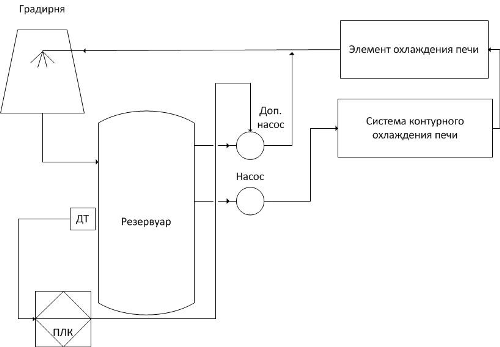 |
Figure 5.2 - Temperature control system fluid
If the temperature limit is exceeded, the PLC generates a control signal includes an additional pump for pumping water on a path to bypass the furnace directly into the cooling tower. This reduces the temperature of the liquid in the tank. Upon reaching the permissible temperature and normalization cooling, the PLC switches off the additional pump and the fluid circulates through the normal circuit. This provides an increased level of temperature control fluid, while minimizing power consumption for cooling due to its periodic inclusion of the additional pump.
5.4 Development of a system of automatic adjustment of the rigidity of the coolant.
Adjusting stiffness coolant made ??permanent control electrical conductivity of water. Will use the analog conductivity sensor. Lowering the water hardness is by purging the tank softer water (automatic drain tap water and topping relaxed).
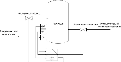 |
Figure 5.3 - Automatic adjustment of water hardness
If you exceed the level of rigidity of the liquid, the PLC opens the solenoid drain and drain the water from the tank. When the water level falls below normal in the tank, an alarm system and automatic level control fills the tank. An important condition is the greater flow of water in the tank than draining into the sewer. This is achieved by setting drain solenoid smaller diameter than the pitch.
After purging of the tank and the normalization of the rigidity of coolant, the PLC closes the drain valve and the system automatically adjust the level of the liquid refills the tank to the required level.
5.5 Development of structural and functional circuits.
Fig. 4.4 shows a block diagram of an automatic control system of cooling.
Description of abbreviations:
RU1, RU2 - coolant level in the reservoir;
DC - conductivity sensor;
DT - fluid temperature sensor;
MAB - analog input module;
PLC - programmable logic controller;
ISP - control and display of the operator;
IF - inverters motor control;
ME1, ME2 - executive power arrangements;
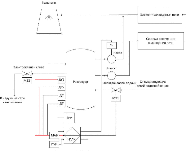 |
Figure 5.4 - Block diagram of the automatic cooling system
(Animation: 6 shots, 7 cycles of repetition, 117 KB)
This block diagram is a combination of block diagrams automatically adjust the level of the liquid automatically adjust water temperature, automatically adjusting the stiffness of coolant, so the description can be found in paragraphs 3.2, 3.3 and 3.4.
Fig. 5.5 shows a functional diagram of the automatic control system of cooling.
The functional diagram (Figure 3.5) the regulation of the level of the coolant system carries 1. The system includes a standard automation components - liquid level sensors (1-1, 1-2), secondary indicating instruments (1-3 and 1-4) and controller with setpoint (1-5 and 1-6), the actuator with the regulator (1-7). When falling liquid level sensor is triggered, and the lower level (1-2), the microcontroller sends a signal to the solenoid valve (1-7) which opens the supply of softened water from the existing water supply networks. The water is supplied to the moment of filling the tank and sensor response of the upper level (1-1). Thereafter, the microcontroller stops generation control to the solenoid valve and close it.
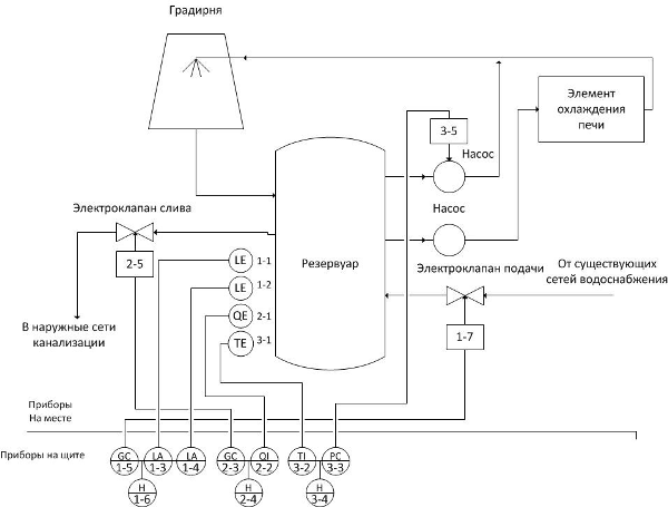 |
Figure 5.5 - Functional diagram of an automatic cooling system
Regulation of the coolant system performs 2. It comprises a conductivity sensor (2-1), a level indicator (2-2), and the controller also controls a manual dial (2-3 and 2-4) and the actuator (2-5). If you exceed the level of rigidity of the liquid, the PLC opens the solenoid drain (2-5), and drain the water from the tank.
Temperature control and its stabilization system performs 3. It includes a temperature sensor (3-1), the temperature indicator (3-2), and manual control dial (3-3, 3-4) and the regulator (3-5). If you exceed the limit of the temperature sensor is triggered and (3-1), the PLC generates a control signal includes an additional pump (3-5) for pumping water on a path to bypass the furnace directly into the cooling tower. Upon reaching the permissible temperature and normalization cooling, the PLC switches off the additional pump (3-5), and the fluid circulates through the normal circuit.
Overview of results and conclusions
The task of the master's work is to design a system to track and control temperature, level and composition of the coolant. The result was made:
- The analysis of circulating cooling furnaces at steel plant;
- A comparative analysis of the existing automation solutions;
- A system for automating the process of cooling production elements rolling mill;
- Matched set of technical tools
List of sources
- Андоньев С.М., Жильцов В.М., Левин Г.М. Особенности промышленного водоснабжения – Киев: Стоитель, 1981.– 248 с.
- Рациональное использование и защита водных ресурсов в черной металлургии / Г.Н.Красавцев, Ю.И. Ильичев, А.И.Кашуба –М.: Металлургия, 1989. – 285 с.
- Аксенов В.И. Замкнутые системы водного хозяйства металлургических предприятий – М.: Металлургия, 1991. – 126 с.
- Буторина И.В. Возможные пути решения проблем водопотребления на металлургических предприятиях Украины // Сталь-2005 – № 2 – с. 91-95.
- Абрамов Н.Н. Водоснабжение предприятий черной металлургии [электронный ресурс]. – Режим доступа: http://www.bibliotekar.ru/spravochnik-15/144.htm
- Белевцев А.Н., Белевцев М.А., Мирошкина Л.А. Процессы и аппараты очистки воды в металлургии [электронный ресурс]. – Режим доступа: http://www.knigafund.ru/books/42847