
Abstract
Content
Introduction
Creation and development of new technologies and production processes, increase the cost of water and energy resources, the strengthening of measures aimed at protecting the environment, have led to increased demand for measurement of flow of water and other fluids flowing in pressure and non-pressure pipelines. At present there are a large number of flow meters that use different methods of measuring flow, differing scope and metrological characteristics. Are the most promising methods of flow measurement using ultrasonic waves. This is due to the fact that acoustic waves and vibration are versatile carriers for the status of various objects. Easy light-receiving ultrasonic waves combined with the ability to spread in almost all environments allow wide use of ultrasonic flowmeters for measuring liquid flow in pipes.
Purpose and objectives
Purpose of master's thesis is to theoretically justify the structure and explore the metrological characteristics of the ultrasonic flow meter of drinking water for pressure pipes of large diameter. In the process it will be necessary to solve the following problem:
— to analyze the structure of pressure pipelines and pumping stations, the structure of the liquid flow in full pipes;
— to Analyze the methods and methods of flow measurement in the pressure fluid conduits of large diameter;
— to analyze how to implement the method of ultrasonic measurement of fluid flow in large diameter pressure lines;
— to analyze the existing structural scheme of ultrasonic flow meters;
— to analyze the influence of the main parameters of pressure pipelines to the metrological characteristics of the ultrasonic flowmeter;
— to put the requirements for ultrasonic flow meter and to make the task of designing the structural and functional flow diagrams;
— to develop structural and functional diagram of an ultrasonic flow meter;
— to develop and explore the model of ultrasonic flow meter;
Ultrasonic flowmeters. The principle of operation
Principle ultrasonic flowmeter is based on the fact that the propagation of ultrasonic vibrations in a moving medium, the velocity of ultrasound in the fixed coordinate system (pipe wall) equal to the vector sum of the velocity of ultrasound for medium and velocity of the medium relative to the pipeline. Therefore, if the pipeline are two piezoelectric transducers emitting ultrasonic oscillations downstream and upstream, and respectively two ultrasonic receiver located at the same distance from the emitter, then the fluid flow in the pipeline in the two ultrasonic signals coming channels to receivers with the acoustic difference stroke, the magnitude of which depends on both the fluid velocity.
Ultrasonic flowmeter principle may be based on measuring the time interval for measuring the phase shift between the ultrasonic oscillations downstream alternately directed against it, and measuring the difference in frequency ultrasonic vibrations generated by a self-oscillating circuit and simultaneously directed downstream and upstream [5].
The methods of implementation of the ultrasonic method to determine the flow rate of liquid pressure lines
For pipes of medium and large diameter preferably use ultrasonic meters, the main advantage is the absence of drag, noise immunity performance. There are three main ways to implement the ultrasonic method for determining fluid flow in the pipeline: transit-time, phase, and frequency [6].
Unit converter and ultrasonic flow measuring system, as well as the nature of his work, strongly depend on whether you are radiating ultrasonic vibrations on downstream and upstream on one or on two different electro-acoustic channels. In this connection, ultrasonic flowmeters are divided into:
— single-line or single-channel;
— Two-beam or dual-channel.
In the first case converters somewhat simpler, but the measuring circuit are usually more difficult as the need arises in the storage device and switching to the piezoelectric radiation reception. In addition, there are difficulties in measuring circuits fazometricheskih in connection with multi-scale phase meters. On the other hand, in the double-beam instruments error will occur if both of the electroacoustic channel will be observed uneven temperature or different medium composition. Phase flow are both single beam and double beam, frequency and pulse meters, usually made double-beam [1].
Let's discuss each of these measurement method of ultrasonic flowmeters.
Phase ultrasonic flowmeters.
Phase called ultrasonic flowmeter, based on dependence of the phase shift of ultrasonic vibrations generated by piezoelectric elements receiving from the propagation time difference of these fluctuations the same distance downstream of the moving fluid or gas against it.
In single flowmeters large variety of different piezoelectric elements to the switching circuit for receiving the radiation, in particular, circuits with simultaneous ultrasonic sending short packets, and simultaneous switching of piezoelectric elements with radiation reception. One possible scheme phase ultrasonic flowmeter shown in Figure 1.
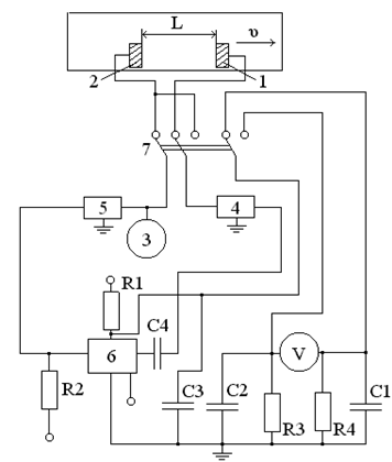
Figure 1 — Diagram of the single-channel phase meter, 1, 2 — a piezoelectric vibrator, 3 — high-frequency generator, 4.5 — amplifier, 6 — phase meter, 7 — Switch
In conduit has two piezoelectric vibrator 1 and 2. One of them, say one in active time using the mechanical switch 7 is connected to a sinusoidal high-frequency generator 3 and the electric oscillation creates ultrasonic vibrations in the fluid stream. Other vibrator receives ultrasonic vibrations in the fluid past the distance L, and converts them into the output electrical signal, then enters the amplifier 4, which in addition to amplification using more limiting stage converts a sinusoidal square wave. Recent served on the phase meter 6. Simultaneously, the generator 3 is continuously connected to the second amplifier 5 (also limiting stage), from which the square wave is also fed to phase meter 6.
Depending on the phase shift changes the voltage value to which the charging capacitor C1, and hence the rate of charge. Once the capacitor is charged, the switch 7 is transfer, whereby the vibrator 1 is generated and oscillator 2 — the ultrasonic vibrations, instead of the capacitor C1 and the capacitor C2 is connected.
Mechanical switch limits the costs due to the rapidly changing measurement light switching frequency (about 10 Hz), achieved with it, while, as the frequency should be at least 3 ... 4 times higher than the frequency of the measured process. In addition, the mechanical switch is the source of the parasitic capacitive connection between the vibrators, as well as the "noise" that can lead to additional errors. Therefore, schemes have been developed phase ultrasonic flowmeter using electronic switches. One such scheme is shown in Figure 2. Here the connection of the radiating dipole with a generator G and receiver amplifier A vibrator is via electronic keys K1, K2, K3 and K4, made in the form of a multi-stage amplifiers (to achieve the desired attenuation in a locked channel) with a low pass capacity.
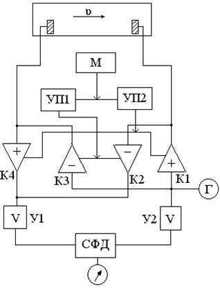
Figure 2 — Single-channel phase meter with an electronic switch: M — flip-flop; UP1, UP2 — control amplifier, K1, K2, K3, K4 — electronic key, U1, U2 — amp; SFD — simultaneously — phase detector
Switching valves carries M-flop with two control amplifiers UP1 and UP2, creating a symmetrical square wave voltage input at the K1 and K4 or K2 and K3.
Frequency of these oscillations is equal to the switching frequency valves, and hence vibrators. Currently included keys K1 and K4 ("+" sign), and switched K2 and K3. The rest of the circuit, consisting of sync - SFD phase detector, which receives the square wave from the amplifiers U1 and U2, works the same as in the previously discussed phase meter. Presence switch both mechanical and electronic devices complicates the structure, and in particular their circuit phasemetrical.
This disadvantage can be eliminated if the pipeline to install two pairs of oscillators so that a pair of emitter continuously creating vibrations directed upstream, and the other - the upstream. L distance between the transmitter and the receiver must be the same for each pair. The oscillation frequency in such a device is usually high in order to provide direction to avoid radiation and vibration transmission to the neighboring vibrator. This phase meter to meter will arrive continuously two sinusoidal oscillations, the phase shift between them proportional to the flow velocity.
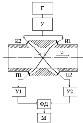
Figure 3 — Diagram of dual-phase flow G — generator, U, U1, U2 — amplifier; I1, I2 — emitter, P1, P2 — the receiver PD — phase detector, M — indicating device
Ultrasonic vibrations generated by emitters I1 and I2, pass through the acoustic waveguide from the organic glass is refracted upon entering the fluid passes through the latter, and by receiving the acoustic waveguide come to the receiving piezo P1 and P2, the latter forming a sinusoidal voltage, the phase difference between the which is proportional to the flow velocity. Each of the piezoelectric elements P1 and P2 connected to its amplifier U1 and U2 consists of four stages of resonance. One of the amplifiers has a bridge-type phase shifter associated with the second and third amplification stage two repeater cathode and serves to compensate the initial phase shift between channels of the receiving transducer. Yield both amplifiers is associated to a phase. Detector PD, in which both of the compared voltages are in phase the total ohmic resistance and stacked on it. The total voltage on the last depends on the phase shift between the oscillations passed on downstream and upstream. This voltage is detected and fed to a galvanometer M, from which the voltage supplied to the electronic potentiometer.
As has already been said, the testimony phase flow depends on the velocity of sound in the environment. To eliminate this dependence, suggested the inclusion of a special unit, which converts a voltage proportional to the phase shifts in any inversely proportional quantities, such as currents, and then subtracted these values.
However, the attempt to realize this idea did not give a positive result, as the existing instruments do not measure the full phase-shift, and just parts of them.
Another way to eliminate the influence of the speed of sound on the instrument reading is based on the phenomenon of refraction of the ultrasound beam incident at an angle on the boundary between two media (liquid - material turbo). Material turbo is selected so that the phase change on the receiving vibrator caused by changing the speed of sound in the stream and its accompanying change in the angle of refraction, offset error of the instrument by changing the speed of sound [1].
Transit-time ultrasonic flow meters
Called transit-time ultrasonic flow meters that measure the time difference between short pulses moving in the direction of flow and against it on the length of the path.
Transit-time flowmeters, in most cases operate on single channel and very short pulses with a duration of 0.1-0.2 ms sent in opposite directions simultaneously or alternately with a frequency for example 0.5 kHz.
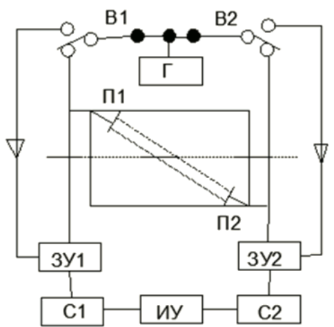
Figure 4 — Diagram of a single-channel transit-time flowmeter
Generator G generates pulses having a duration of 0.2 ms and a repetition rate of 800 Hz, which with the help of vibrators B1 and B2, operating at a frequency of 400 Hz, fed alternately to the pressure cell to P1 and P2. Latest sent to the liquid quickly damped ultrasonic pulses and vibrators B1 and B2 include chargers CD1 or CD2. From the generator G at the same time has a pulse to piezoelement P1 and the impulse to trigger CD2. placing it in the active state of conduction. In this case, the device is C2 ramp voltage is generated in the course of time, the passage of ultrasound through the measured substance. The maximum value of this voltage is proportional to the time. At the time of the arrival of the ultrasonic pulse to piezoelement P2 C2 device is turned off. In the same way for the passage of the ultrasonic pulse upstream from P2 to P1 C1 device generates a voltage proportional to the time. The voltage difference measured by the DUT. This cycle is repeated 400 times per second.
This method has in recent years the most widely used. This is due to its high accuracy in a wide range of variation of sound-conducting medium of any costs low (about 1-3%) of gaseous and solid inclusions, low inertia (0.1-1 s), capable of measuring pulse rate and pulse streams, high sensitivity Change flow rate (1-2 mm/s) [3].
Frequency ultrasonic flowmeter
Frequency ultrasonic flowmeters are divided into frequency-batch and pulse frequency.
In ultrasonic frequency vibrations packet flow meters, directed by and against the flow velocity by the pulse circuit are converted to such fluctuations with periods equal to twice the ultrasonic transit time between the vibrators on the downstream and upstream. The measured frequency difference between the received device oscillations is directly proportional to the speed or flow of liquid.
Block diagram of such a flow is shown in Figure 5.
Figure 5 — Animation of the dual-frequency packet ultrasonic flowmeter - count of frames - 10, size - 130 KB; number of cycles of repetition - permanently
Generator G, creating a sinusoidal high frequency (10 MHz), delivers the latest via modulators M1 and M2 for the radiation vibrators I1 and I2. The first sends ultrasonic vibration angle? to the velocity. These oscillations are seen receiving vibrator P1, located at a distance L from the vibrator I1. Once the first vibration input at the receiving vibrators P1 and P2, and then pass through the amplifiers V1 and V2 and the detectors D1 and D2 made modulators M1 and M2, the latter operating in the trigger mode, bar extending to the oscillation generator I1 and I2 vibrators and radiating ultrasonic oscillations terminate. It will resume in those moments when the last packet of the first ultrasonic vibrations reach the receiver dipoles P1 and P2 and the latest generation of electrical oscillations stop. At these moments, modulators M1 and M2 are rediscovering the passage of electrical oscillations from the generator to the emitters I1 and I2, and the process repeated. It is easy to see that time and the time of "silence" of vibrators I1 and A1 will be equal to T1, and the operating time and the time of "silence" of vibrators I2 and P2 is equal to T2. The frequency of the first cycle is obviously f1budet 1/2T1, and the second will be equal to f2 1/2T2. Thus, the input mixing stage SM receives the two vibration processes: one with a frequency f1 and a second frequency f2. The output stage obtain the frequency difference f1-f2.
Is highly valuable that the difference frequency (f1-f2) is proportional to flow rate and is independent of the velocity of sound.
It would be useful to increase the value of the measured frequency difference f1-f2. This would reduce the time required for measurement f1-f2, and hence improve the performance of the device.
To eliminate possible crosstalk in two adjacent acoustic channels are sometimes used in different carrier frequencies, such as 85 and 135 kHz [1].
Findings
In preparation of his thesis I analyzed the ways of the ultrasonic flow measurement of liquid in the pressure of large diameter pipes.
Among the methods most widely used in recent years received a transit-time method.
This is due to its high accuracy in a wide range of costs of any sound-conducting media with low (about 1-3%) of gaseous and solid inclusions, short response time (0.1-1 s), the ability to measure pulse rate and pulse flows, High sensitivity to changes in flow rate (1-2 mm / s).
In writing this essay master's work is not yet complete. Final completion: December 2013.
List of References
1. Кремлевский П.П. Измерение расхода и количества жидкости, газа и пара. — М.: Изд-во стандартов, 1990. — 192 с.
2. Ультразвуковые расходомеры и система учета на их основе / Вячеслав Близнюк, Владимир Костылев, Валерий Сорокопут, Анатолий Стеценко, Андрей Стеценко - Измерительная техника
3. Бесконтактные методы измерения расхода жидкости в напорных и безнапорных трубопроводах / Громов Г.В., Озеров А.В., Шафрановский М.Н. — Мир измерений
4. Накладные и врезные расходомеры в коммерческом учете учете: желаемое или действительное / Гришанова И.А. — Фирма «СЕМПАЛ»
5. Объемные расходомеры / Катыс Г.П.:книга, М. — Л., издательство «Энергия», 1965, 88 с. с черт.
6. Спектральная обработка сигналов в ультразвуковых расходомерах систем водоснабжения / Никандров М.В. — Диссертация
7. Погрешности ультразвуковых расходомеров от расширения и деформации трубопровода при перепадах температуры и давления транспортируемой жидкости / Чернов Б.А. — Алматинский университет энергетики и связи
8. Ультразвуковая расходометрия на примере тепловодосчетчика СВТУ-10М: мнения и факты / Покрас C.И., Покрас А.И., Гришанова И.А — Фирма «СЕМПАЛ»
9. Proving Liquid Ultrasonic Flow Meters for Custody Transfer Measurement / Smith Meter® Liquid Ultrasonic Meters — FMC Technologies
10. Башутин Ю.П. Новая эра в измерении расхода по перепаду давления //Приборы и системы управления. — 1998. — №5. — с. 54-56