
Abstract
Content
- Introduction
- 1. Theme urgency
- 2. Goals and objectives of the research
- 3. Problem solving and research
- Conclusion
- References
Introduction
In recent years, the trend of mobile traffic growth in video and data[1]. According to research WWRP (Wireless World Research Forum) expected that in 2015 traffic worldwide will be 23 exabytes is similar to that 6.3 billion people will download every day for a digital book[2].
Today there are many operators who use a variety of standards and technologies for creating and implementing wireless networks. So very acute question of their interaction with each other. Of course, there multystandart radioterminaly, as well as a variety of composite network to provide access to multiple services. However, the development of wireless communication systems and is much faster processes of standardization.
1. Theme urgency
Currently there are two most important problems in modern telecommunications[3]:
– significant increase in mobile traffic, with limited frequency resources;
– the virtual absence of common standards;
Solving these problems requires further development of communication systems using radio subsystems, the most important feature of which is suitability for updates through software. This allows flexible adaptation to new standards, largely removing compatibility issues. But more needs and some extra hardware that can support the work simultaneously in several standards, while retaining the ability to interact directly with two or more operators. The optimal solution is the technology Software Defined Radio (SDR)[4, 5], which became especially popular and in demand in recent years [6]. The model primarily focuses on the needs of users, is considered only pleasant part of the device.
2. Goals and objectives of the research
The above determines the relevance of the goal of this work - expanding the application of reconfigurable subsystems and improve the efficiency of resource use heterogeneous networks by improving structures and algorithms multystandart receiver. Improvement is achieved by combining together heterodyne receiver structures and program-conditioned radio single device.This device will reduce the range of the hardware required to implement several telecommunication services by utilizing an integrated set of hardware.
To achieve this goal it is necessary to solve the following tasks:
А) To prove the possibility of the receiver with several standards, which requires:
- Conduct a review of existing technologies, and assess the prospects for their combined use. Decide which standards can be calculated device.
- Suggest a concept mai-multystandart equipment. The existing standard solutions and their suitability for use in the device.
Б) Offer structure and algorithm mai-MUR based SDR. Identify requirements to be met receiver. To analyze the feasibility and efficiency of development.
Object of research: equipment integrated heterogeneous network operators.
Purpose of the research: structures and algorithms multystandart receiver.
3. Problem solving and research
Third generation mobile communication based on the packet data. Third generation 3G network operating on UHF frequencies, typically in the range of about 2 GHz. Of all the existing options are worthy of consideration only the two most common, such as CDMA[7, 8] and UMTS[9]. CDMA (Code Division Multiple Access) - communication technology, usually radio, in which channels have a common frequency band but different PCM.UMTS (Universal Mobile Telecommunications System) designed to upgrade the GSM and widespread, not only in Europe but also in many other regions of the world. Other standards 3rd generation have no prospects and their consideration is not appropriate[10].
For 4G networks International Telecommunication Union approved only two standards that fit the bill - LTE Advanced [11, 12] and Mobile WiMAX 802.16e[13, 14]. LTE (Long Term Evolution) - project was developed by a consortium of technology improvement 3GPP standard mobile data CDMA, UMTS. WiMAX (Worldwide Interoperability for Microwave Access) - telecommunications technology designed to provide universal wireless communication over long distances for a wide range of devices.
To further develop the structure necessary to specify the frequency range used by each standard. In particular, specify the frequency spectrum to transmit data from the subscriber to the base station (Uplink) and from the base station to the subscriber (Downlink). However, since in this paper developed a model of the receiver, it is possible to limit the range of frequencies only channel Downlink. Summary data are presented in chart 1.
Chart 1. - Key Features Standards UMTS,CDMA,LTE та WiMAX
|
Name of technology
|
Generation (3 or 4)
|
Frequency spectrum to transmit data. Only Downlink, MHz
|
The minimum width of a single channel, MHz
|
The maximum data rate (in theory)
|
|
|
Uplink, Мbit/с |
Downlink, Мbit/с
|
||||
|
UMTS
(W-CDMA)
|
3G
|
1958-2025
|
5
|
27 |
73,5
|
|
CDMA
|
3G
|
824-848
|
1,25
|
1,8 |
3,1
|
|
LTE
|
4G
|
2500-2540
|
20
|
172,8 |
326,4
|
|
WiMAX
|
4G
|
2600-2640
|
20
|
20 |
20 |
After analyzing the above table it can be concluded that all of our favorite technologies are prerequisites for integration into a single device, due to the transfer of spectrum in a compact area without overlapping them. Such an approach promotes a sufficiently high speed ADC capable obroblyuvaty total group signal.
Implementation multystandart (combining multiple technologies into a single device) can be implemented by using two principles which are multystandart terminals:
- Switch between multiple technologies.
- Parallel operation of several technologies.
Both variations are quite different from each other. But when we say "multystandart equipment" are referring to switching between multiple technologies. To avoid confusion, we introduce a separate term for the second variation - mai-multystandart (Latin multiple activa iunctio - multiple active compounds), which provides for parallel operation of several technologies. Designed receiver will work on a mai-multystandartnisti.
At the moment there are not many examples multystandart equipment:
But all the above devices are one and the same flaw. In particular, they can not simultaneously receive data from several operators. To solve this problem, this paper designed structure mai-multystandart receiver (the mai-MUR) that supports multiple active connections. In other words, the user will be able to receive data from several mobile operators simultaneously. As the core technology is proposed to use SDR, to offer a model of mai-MUR using 3 channels (see Figure 1).
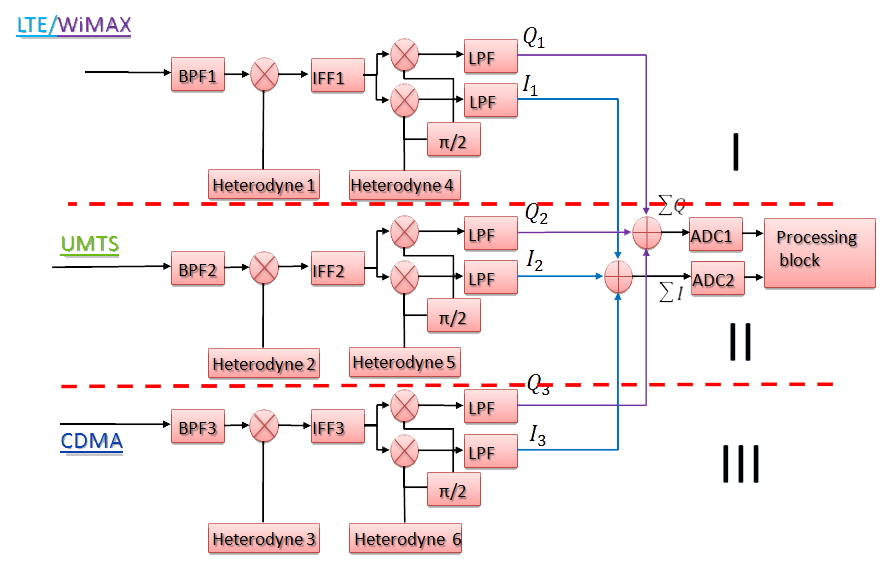
Figure 1 - Block diagram of mai-MUR Level 1
Although identified the 4 most promising standards, using only three channels. This is due to the frequency bands LTE and WiMAX, which are very close to each other, so the first channel will handle compatible signal. The second channel is designed to process signals from the network, based on standard UMTS. And third, to those based on technology CDMA.
In contrast to standard SDR-receiver[16, 17],
чfrequency of each channel in a fixed range. Thus, as expected, the
device only works with strictly defined set of standards
reconfiguration frequency we do not need[18].
The structure of the device there are two ADCs, each of
which handles the total signal I, Q and the second of the three
channels[19,20].
This is necessary to maintain the desired speed setting signal
processing. Demodulation and further digital processing is carried out
by specialized controllers using selected software[21, 22].
Primary and secondary transfer spectrum inhibition of the negative component forming signals I and Q, as well as their association and analog-to-digital conversion is performed by hardware. Double transfer spectrum, as a result reduces the frequency quantization, and thus to reduce the requirement for speed ADC.
The initial transfer of spectrum produced by the oscillator and multiplier[23]. Just be aware that to transfer the signal to filter out noise and specular channel used for this purpose preselector. Secondary transfer of spectrum will be carried out similarly to the primary. Formation of the I and Q signals occurs simultaneously with the processes of secondary transfer spectrum, which involved local oscillator and phase shifters. Combining signals I and Q channels carry different adders. Treatment of each of the streams produced by two parallel ADC. Further signal processing is realized by software, which provided processing unit.
The receiver meets several important factors. Firstly, its structure is organized in such a way that it can support multiple active connections. Secondly, as the device operates with 4 different standards included band channel needed for each of them. In this case, the minimum channel bandwidth - 40 MHz. It is required for most "expendable" standards LTE and WiMAX. This band signal just satisfied with the stock requirements of UMTS and CDMA2000. Thirdly, it is necessary spectrum signals do not overlap, as when taken, and when moving to lower frequencies, as demonstrated in the following example.
And as each of the three channels of the same signal transduction occur, for example, consider only channel II. The signal from the UMTS network enters the preselector (indicated in the diagram PF2), which weakens all received signals in this band than we need.
As shown in Figure 2 Structure convert the signal consists of two stages. The first time is a significant reduction in frequency. It is necessary for the transformation of the second, during which the signals are transferred to the region of zero bandwidth. Consider the algorithm in more detail. The signals from the networks UMTS, CDMA signal and compatible LTE / WiMAX coming to preselector (in the diagram labeled PF1, 2.3). They all received signals minimaze power than we need.
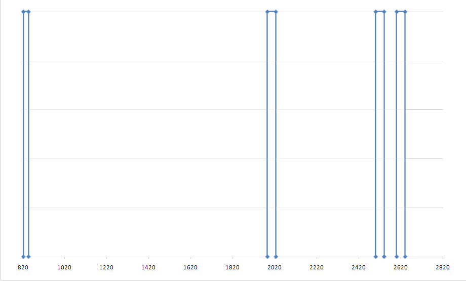
Figure 2 - Location of the four signal networks in the frequency range for processing at the receiver
Then, the transfer of the signal from the gigahertz range in MHz with appropriate mixers and LO (1,2,3). LPF1, LPF2, LPF2 provide suppression image rejection, arising after the first transfer of spectrum. Let us consider in more detail the transformation with decreasing frequency. Event RF signals (RF) signal and local oscillator (LO). The output signal is formed intermediate frequency (IF). The output signal contains both the total and difference components of the input signals. Mathematically, the output signal can be described at the level of harmonic components (1) - (3):
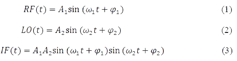
Using trigonometric equations can be transformed equation (3) to the form that contains the sum and difference frequencies:

Thus the output contains a summary and difference components of the input signals. Additional filtering of the input and output necessary to attenuate unwanted components of the signal to obtain the necessary characteristics. For our chosen frequency (see Chart 1.) With regard to filtration obtain frequency signal at the output of the first converter (see Chart. 2, Fig. 2).
Chart 2. – Frequency standards UMTS, CDMA, LTE and WiMAX spectrum after the first transfer
|
Technology
|
Frequency signals |
|||||
|
Primary transfer spectrum |
Secondary transfer spectrum |
|||||
|
Primary frequency, MHz
|
Frequency oscillator, MHz
|
Final rate, MHz
|
Secondary frequency, MHz
|
Frequency oscillator, MHz
|
Final rate, MHz
|
|
|
CDMA
|
824
|
637 |
187 |
187
|
274 |
-87 |
|
848
|
637 |
211 |
211
|
274 |
-63 |
|
|
UMTS
|
1985
|
1700 |
285 |
285
|
338 |
-53 |
|
2025
|
1700 |
325 |
325
|
338 |
-13 |
|
|
LTE
|
2500
|
2090 |
410 |
410
|
400 |
10 |
|
2540
|
2090 |
450 |
450
|
400 |
50 |
|
|
WiMAX
|
2600
|
2040 |
560 |
560
|
500 |
60 |
|
2640
|
2040 |
600 |
600
|
500 |
100 |
|
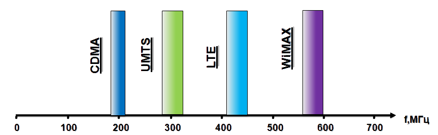
Figure 3 - Location of all signals in the frequency range after the first transfer in the MHz range
After LPF (1,2,3) signal is transferred to the destination at low frequencies. Payment is made by the same formula as the first time. The process occurs through multipliers (4,5,6,7,8,9), phase shifters (1,2,3) and LO (4,5,6). Common-mode signal is generated using multipliers (5,7,9) and LO (4,5,6). Shifter (1,2,3) and multipliers (4,6,8) form a quadrature signal. In the next step I signals from all three channels are summarized and presented to the ADC1, just created and the total signal is fed to the Q and ADC2.
For the second transformation effect of the phase difference is significant, because in subsequent calculations take into account the phase shift of ninety degrees. Thus Formula 4 is divided into two formulas:
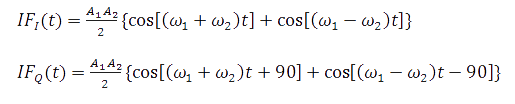
As you can see from the result, specular component spectrum can pryhnichyty by the addition of component I to component Q shifted relative to the first ninety degrees. This procedure can be implemented using filter Gilbert to Q components of the proposed book software.
Further processing of the selected signal filtering and demodulation is also offered to carry out the program by applying for this alleged software. The results of calculations of spectra above rules are given in chart 2 and Figure 4.
Figure 4 - Signals after transferring to the area of the ADC
(Animation: 3 frames, the delay between frames 1, the number ofcycles of repetition - 50, size 50 KB, created using the GifAnimator)
The possibility to realize the integration of the various technologies in a single device. Most bottleneck in the project is the ADC. But thanks to the chosen structure and algorithms, able to bring variety to the width of all signals in the 200MHz, which can run modern ADC[24]. Based on the data selected a specific device type (AD 9467-200) with the following parameters:
1) Bit - 16 bit.
2) MPLS - 200 MHz.
In the future, if necessary, can realize possibility of dynamic management of spectrum. This radio system will adapt to external conditions that increase the efficiency of RF signals. The very model of mai-SMEs in this case would have to treat cognitive radio (Cognitive Radio, CR). [3, 25]
Conclusion
- The review of existing technologies and selected standards which operates the device.
- The concept mai-multystandart equipment.
- The structure and basic algorithm mai-MUR based SDR.
- The requirements for the designed receiver and confirmed the possibility of their performance.
- An example implementation for a particular case.
Master's thesis devoted to actual scientific problems - the expansion of the application of reconfigurable subsystems and improve the efficiency of resource use heterogeneous networks by improving structures and algorithms multystandart receiver.
Further studies focused on the following aspects:
- Decomposition of the hardware and software developed device.
- Research developed by mai-multistandart receiver simulation methods.
- Develop recommendations for use of the device in telecommunications.
- Evaluation of new scientific results obtained during the study.
When writing this master's work is not completed. Final completion: December 2013. Full text of the materials can be obtained from the author or his manager after that date.
References
- Гепко И.А., Олейник В.Ф., Чайка Ю.Д., Бондаренко А.В., Современные беспроводные сети: состояние и перспективы развития [Электронный ресурс] / Современные беспроводные сети, - Режим доступа: источник.
- Tafazolli, R., Technologies for the Wireless Future, volume 2, Wireless World Research Forum, (WWRF), John Wiley & Sons, Chichester, England, 2006.
- Friedrich K. Jondral, Software-defined radio: basics and evolution to cognitive radio, EURASIP Journal on Wireless Communications and Networking, Karlsruhe , Germany, August 2005, pp. 275-283.
- SDR forum [Электронный ресурс]. – Режим доступа: источник.
- Tuttlebee W., Software Defined Radio – Enabling technologies / Walter Tuttlebee. – John Wiley & Sons, 2002. – pp 428 .
- Reconfigurable Radio Systems (RRS): SDR Reference Architecture for Mobile Device //ETSI TR 102 680 V1.1.1 (2009-03).
- Diakoumis Gerakoulis, Evaggelos Geraniotis, CDMA: Access and Switching: For Terrestrial and Satellite Networks (Hardcover) Diakoumis Gerakoulis, Evaggelos Geraniotis 2001.
- Kiseon Kim, Insoo Koo, СDMA systems capacity engineering — Germany, August 2005, pp. 375-383.
- Кааранен Х. Сети UMTS. Архитектура, мобильность, сервисы ⁄ Х. Кааранен, А. Ахтиайнен, Л. Лаитинен, С. Найян, В. Ниеми. – М.: Техносфера, 2008 – 468 с.
- Алексеев В., Можайков Д., Высокоскоростные сети мобильной связи поколения 3G. Часть 2. Технологии сетей мобильной связи HSPA. // Алексеев В., Можайков Д. - М.: «Сов. радио», 2011. Выпуск 2. С. 5–12.
- Moray Rumney, LTE and the Evolution to 4G Wireless: Design and Measurement Challenges. – Agilent Technologies, р 557 .
- Farooq Khan, LTE for 4G Mobile Broadband: Air Interface Technologies and Performance. – Cambridge University Press, р 492 .
- Коржов В., Беспроводные технологии передачи данных - стандарт радиодоступа WiMAX [Электронный ресурс] / Журнал "Computerworld", - Режим доступа: источник.
- Васильев В.Г., Технология фиксированного широкополосного беспроводного доступа WiMAX [Электронный ресурс], - Режим доступа: источник.
- Хабрахабр – самое крупное в Рунете сообщество людей, занятых в индустрии высоких технологий [Электронный ресурс]— Режим доступа: источник .
- Mitola J., “The software radio architecture,” IEEE Communications Magazine, pp. 26–38, May 1995.
- Kenington P. B., RF and Baseband Techniques for Software Defined Radio / P. B. Kenington // Artech House,2005— 352 pp.
- Сиверс А.П., Проектирование радиоприемных устройств. / Сиверс П.А. — М.: «Сов. радио», 1976. — 487 c.
- Windisch M. , Fettweis Blind G. , I/Q-imbalance parameter estimation and compensation in low-IF receivers [Электронный ресурс]. – Режим доступа: источник.
- I/Q Signal Mismatch Theory [Электронный ресурс]. – Режим доступа: источник.
- Лайонс Р., Цифровая обработка сигналов / Р Лайонс – М.: Бином-пресс, 2000 – 300 с.
- Лайонс Р., Цифровая обработка сигналов / Ричард Лайонс. – М.: Бином, 2006 – 656 с
- Поляков В. Т., Радиолюбителям о технике прямого преобразования / В. Т. Поляков — М.: Патриот, 1990 — 264 с.
- Богданович Б. М., Радиоприемные устройства с большим динамическим диапазоном / Б. М. Богданович — М.: Радио и связь, 1984 — 176 с.
- Sinisa Tasic, HF SDR (Software Defined Radio) receivers [Электронный ресурс] / Tasic Sinisa — Режим доступа: источник.