
Abstract
Content
- Introduction
- 1. Theme urgency
- 2. The purpose and objectives of the research, the expected results
- 3. The basic principles of quadrocopter’s flight stabilization
- 4. Experimental studies
- Conclusions
- List of sources
Introduction.
In modern aircraft modeling the new trend is to build a multicopter – unmanned aerial vehicles (UAVs) with an even number of rotors that rotate in opposite diagonal directions. When the UAV contains four engines, it is called quadrocopter. Nowadays, the main trend is the creation of a small unmanned quadrocopter. The main reasons of this are the ability to easily control and maneuverability. Quadrocopter has a great demand among the modelers, but also finds its application in the professional field, such as the police or the army. It has been already existed quadrocopters for delivering mail to the addressee and for making panoramic shots of the events.
1. Theme urgency
The need to stabilize the flight of quadrocopter follows from the principle of its operation. For example, the flight of the aircraft and airframe is stable due to their constancy, i.e. the ability to recover without pilot intervention kinematic parameters of the unperturbed motion and return to the original mode of flight after the termination of the disturbance. The quadrocopter does not have this attribute, at the time of slightest external action it starts the uncontrollable decline
.
2. The purpose and objectives of the research, the expected results
The purpose of master's work is development and research of the electronic system that stabilize the flying of quadrocopter.
The main objectives of the study:
- Analysis of methods of quadrocopter’s stabilization of flight.
- Research and selection of inertial sensors.
- Analysis of the available methods for processing data, that was received from inertial sensors.
- Creating an algorithm of stabilization, which is based on these studies.
- Development of quadrocopter’s bench model.
Object of research: an unmanned aerial vehicle – quadrocopter.
Subject: the aircraft’s determination of the absolute position in space (angles, height, linear displacement).
3. The basic principles of quadrocopter’s flight stabilization
In order to stabilize the quadrocopter’s flight effectively it is required to:
- Be able to determine the condition of the system at the moment.
- Have the ability to implement control actions on the system.
- Know what state of the system will be maintained.
A variety of sensors that provide feedback can be used for determination of the system’s status (e.g. gyroscope, accelerometer, magnetometer, altimeter, etc.). The administering impact is made by changing the render speed of drives. For example, if the UAV is bent to the left side, it is necessary to increase the momentum of the left engine and reduce the momentum of the right.
First of all, for stabilization of the quadrocopter, it is necessary to know the absolute position in space. Stabilization is carried out on a number of parameters: the height, angle, linear movements. The quadrocopter is an aircraft, so for angles of inclination are used aircraft terms: the pitch (in the X-axis plane), tilt (in-plane Y-axis) and yaw (in the plane of the axis Z, Fig. 1).
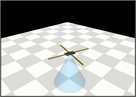
Figure 1 – Animation process rotation about an axis Z (yaw). The basic animation parameters: count of frames – 6; size – 157 kB, the number of cycles of repetition – 7
Let’s use the gyro sensor to determine the roll, pitch and yaw. The gyro sensor is an instantaneous angular velocity about an axis. It is necessary to integrate the readings for determining the angle with the gyroscope, for example, by the methods of rectangles [6]:
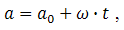
where α – the current value of the angle, α0 – the previous value of the angle, ω – the current value of the angular velocity, t – time between measurements.
But the use of this approach leads to addition the increment and error, that is caused by the inaccuracy of the gyroscope. This will lead to the fact that after some time the calculated value of the angle will be further and further away from the actual value (Fig. 2).
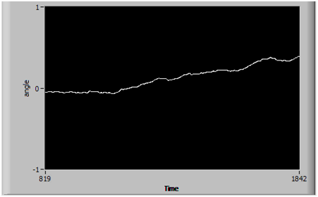
Figure 2 – Uses gyro in resting position
That is why it is necessary to adjust the values of the calculated angles over some periods of time. For this adjustment it is used an accelerometer that measures the projection of the apparent acceleration on the sensitive axis.
But the accelerometer provides accurate values only in a state of rest. During the moving to the real evidence is added its own projection of acceleration and angle "floats". That is why in such a dynamic system as a quadrocopter, the accelerometer is used only for the correction of angles’s value. Also, this leads to another feature. In case of using only the accelerometer it is possible to adjust only roll and pitch angles (align relative to the horizon). But to correct the yaw angle is not possible because of the coincidence with the axis of rotation of the vector G. To solve this problem, it is used a magnetometer (digital compass), which enters another vector in the system [2]. The magnetometer has its drawbacks, the main one of which is the low accuracy. The error can be up to 5 degrees, and near the quadrocopter engines and power supply lines this error will increase.
4. Experimental studies.
To adjust the angle we use a complementary filter, which work is described by the following equation:
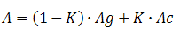
The main task of the complementary filter is to reverse the gyro zero drift and integration errors. The weight of correction value is determined by the filter K.
Figure 3 shows the result of the filter operation for the axis X. As can be seen, the system initially turned 26 degrees, then an additional 6.
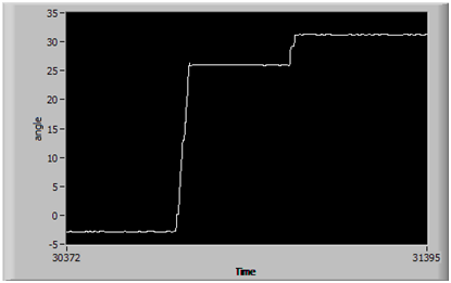
Figure 3 – The result of the complementary filter
The error of the filtered values of the angle (Fig. 4) is ± 0,05 °, which is a great result for stabilizing the flight quadrocopter.
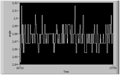
Figure 4 – The result of the complementary filter at standstill
Findings
- For stabilizing the flight of quadrocopter it is necessary to know the absolute position in space, especially the angles roll, pitch and yaw.
- For determining the angles the use of one gyro is not enough. It must be entered correction using the accelerometer and magnetometer to obtain accurate data.
- The use of the complementary filter has a high efficiency, while it does not spend a lot of computational resources.
This master's work is not completed yet. Final completion: December 2013.
List of sources
1. Система управления БПЛА для полета на малых высотах/ Т.В. Белоцерковский – Национальный технический университет Украины.
2. Building and controlling the Quadrocopter – Pavel Chmelar – Number 5, Volume VI, December 2011.
3. Design and control of quadrotors with application to autonomous flying – Samir BOUABDALLAH – ingenieur d'etat, Universite Aboubekr Belkaid, Tlemcen, Algerie
de nationalite algerienne
4. An Introduction to the Kalman Filter – Greg Welch, Gary Bishop – Department of Computer Science. University of North Carolina at Chapel Hill Chapel Hill, NC 27599-3175 Updated: Monday, July 24, 2006.
5. Разработка управляющих программ промышленных роботов/ А.С. Климчик Р.И. Гомолицкий Ф.В. Фурман К.И. Сёмкин – Курс лекций для студентов – C. 131
6. Самарский А.А., Гулин А.В. Численные методы: Учеб. пособие для вузов. – М.: Наука. Гл. ред. физ-мат. лит., 1989. – 432 с.
7. Основы построения бесплатформенных инерциальных систем/ В.В.Матвеев, В.Я.Располов – СПб.: ГНЦ РФ ОАО «Концерн «ЦНИИ «Электроприбор», 2009. – 280 с.
8. Ampersant [Электронный ресурс]: Ультразвуковой дальномер – Электронные данные. – Режим доступа:http://www.ampersant.ru/ultra/Дата доступа: апрель 2013. – Загл. с экрана.
9. Разработка ультразвукового измерителя дальности / А.В. Бурдуков // Дипломный проект Государственный университет аэрокосмического приборостроения. – 2010. – С. 17 – 22.
10. Strapdown inertial navigation system. Part 1 – Navigation equations – Albert Ortyl, Zdzislaw Gosiewski – Journal of thheoretical and applied mechanics – 1,36,1998 – C.83–96.