
Abstract
The content of the abstract
- Introduction
- 1. Relevance of the topic
- 2. Analysis of the device's features and operation of the research
- 3. The goals and objectives of the study
- 4. Theoretical analysis of the properties of devices accelerated braking asynchronous motor
- Findings
- References
Introduction
The basis of the technical process of the coal mines is the extensive use of high-performance production systems, equipped with modern explosion-proof electrical equipment. Their implementation provides a significant increase productivity of the enterprise. The high efficiency of coal mining is largely dependent on the efficient operation of mining transport, in particular the pipeline, the value of which is becoming increasingly important due to the increasing power of coal mining machines. At present, commonly used as a downhole drag conveyors, which are adapted to the conditions of operation of mechanized cleaning of the complex. For leading coal mines is characterized by increasing the degree of concentration of mining operations, the growth of loading on the working face, reducing their numbers and a simultaneous increase in the length and advance rates. All of these causes are increasing the load on the mud scraper conveyor. As a consequence, developed and applied in the production of scraper conveyors all great length and with a more powerful drive.
1. Relevance of the topic
From the analysis of design and operating conditions scraper conveyors that run them is accompanied by a high moment of resistance, which creates a chain with scrapers and moved the mountain mass. In addition to this design allows the scraper conveyor clogging by cuttings and jamming the pulling unit, which is a critical impulses drag chain. In order to make the drive to reduce overloads are equipped with non-adjustable hydraulic clutch. Experience has shown that their puskozaschitnoy fluid coupling function performs satisfactorily, has little actual service life, low reliability. With a significant moment of inertia of the rotating parts coupling increases the tensile force in the drag chain at the time of seizure, thus promoting not the defense, and the last impulse.Motor protection is associated with a fluid coupling scraper conveyor downtime caused by types of time – Tornio fill it emulsions, install a new fuse plug. This implies additional material and cost.This is due to the relevance of establishing a more effective method of protection scraper conveyor from locking
2. Analysis of the device's features and operation of the research
Currently, drag conveyors are the most numerous type of vehicle in the mines, tape Conwayize less than 1,6 times the scraper, electric – by 2,5-fold (Fig. 1) Drive belt drive consists of a frame, one or two in-water block (engine – Fluid – Gearbox) and two-wheel drive – governmental stars, transmitting traction on the scraper chain Conway – EPA. [5].
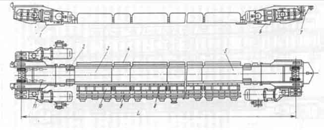
Figure 1 - Typical design of coal mine scraper conveyor: drive head 1, the transition – WIDE section 2 at the head and end of drives, transient Rasht – ki 3 and 5, plowshares 4, 6 drive terminal (or terminal head) line of pans, deflection roller 7 to the direction of the rope safety winch combine harvester guides 8, 9 cable layer boards, boards 10, 11 drag chain, brackets for cable, bracket lamps [5].
Functional element of the conveyor drive specifically designed to slow down the acceleration is fluid coupling comprising a finned pump and turbine wheels, the space between them is filled with emulsion. Influence on the dynamics of a fluid coupling of the electric starter scraper conveyor explained its mechanical response (Fig. 2):
Mm = a1vн2 + a2vн vm + a3vm2 , (1)
where а1, а2, а3 – пconstants for the individual zones of the family of mechanical characteristics; Мm – the moment of the shaft turbine wheel hydraulic clutch; vн, vm – angular speed of the pump and turbine wheels [5].
Close to the rated motor torque turbine wheel hydraulic clutch during start-up can be obtained at an angular velocity of the impeller, which is close to the face. Therefore, at the beginning of the conveyor motor starter accelerates almost no load and at the end of the rotor acceleration jerk movement is transmitted to the drag chain, which is a factor in increasing the dynamic loads in the transmission pipeline.
Sudden braking caused by sudden sticking traction organ is the most dangerous mode of conveyor operation, since its movable elements except static forces which are developed by the motor electromagnetic torque, under the influence of dynamic forces caused by slow moving masses.
Provided that the locking body is instantaneous traction (cross section which is stuck, remains fixed), and in the case of neglecting the mass wedged body portion and resilient traction transmission, i.e. Considering that the mass of the actuator parts that move, is concentrated at a single point, the model assembly line will have the form [6].
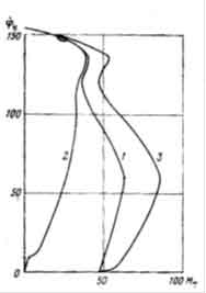
Figure 2 – A set of mechanical properties of a fluid coupling: 1 – working, 2 – Pad, 3 – at work on locking
The nature of the conveyor and the value of emerging efforts after locking determined at the time of the elastic deformation u jammed area pulling unit of length l as a weightless elastic body with a hardness с = E0 / l :
md2u/dt2 + cu - Fдв(v) = 0 , (2)
where m – the total reduced mass of the drive; Fдв – tractive effort in the body by the engine due to the electromagnetic torque; v – velocity of the mass of matter.
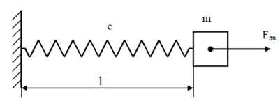
Figure 3 – Design model of the process of locking the assembly line
Determination of maximum force in the pulling body by the engine due to the electromagnetic torque at locking the drag chain is performed using the formula:
Fmax = Fкр + √(F0 - Fкр) + cmvн2 , (3)
where Fкр – force at the critical moment of the motor; F0 – the force exerted by the engine at the beginning of braking; vн – the nominal rate of the pulling unit.
From the expression (3) that at the time of locking the drag chain to stop the turbine wheel hydraulic clutches her entire rotating mass, when added to the weight of the rotor blood pressure, causes significant additional tensile force, increasing the overall tension in the chain.
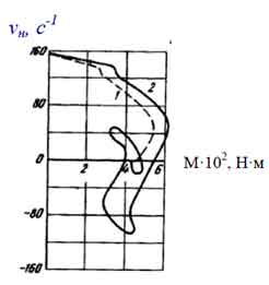
Figure 4 – Experimental step response of a fluid coupling GGE-345 when locking the assembly line [5]
Studies have found that by locking the drawbar organ in the drive belt fitted with a hydraulic clutch, there are fluctuations in the load and the speed of rotation of the turbine wheel coupling (Fig. 4). This is due to the fact that the dynamic load locking cause considerable stretch deformation chains. Wave chain reaction after stopping its turbine wheel spins in a reverse direction, and a fluid coupling working time in opposition mode until the chain will not spend a part of the stored potential energy. Then re-start the turbine wheel and the subsequent locking (Fig. 5). In the low-power fluctuations conveyors quickly fade, however, when the power drive up to 55 kW fluctuations can carry a stationary character with very large amplitudes to melt fuse plugs hydraulic clutches. Thus, the protective effect is the kinematic fluid coupling unit motor and gear shafts by fusion under pressure in the external environment emulsion liquid (which is usually heated up to a temperature greater than 100 0 C) by melting a fusible plug. This action occurs in case of stopping the turbine wheel is provided at the beginning has not occurred gust locking scraper chain conveyor.
Downtime due to failure of the conveyor constitute 5-6% of the total time of mining shifts. Statistical studies conducted by 18 different watches production associations Donbass show that the proportion of downtime associated with finding and eliminating impulse scraped side chains is, on average, 59.3% of the time question–toy scraper conveyors. The largest number of outages due to the breathing of conveyors upper branches of their chains are on – luchasovye and hours of downtime – respectively, 25.8% and 23%. The largest number of outages due to the breathing of conveyors upper branches of their chains are on – luchasovye and hours of downtime – respectively, 25.8% and 23%. The most common flight conveyor downtime due to the breathing of the lower vet – vey drag chain are 2-2.5 hours, but also a lot of downtime duration – tions the 6-8 hour (Figure 1.1) [5].
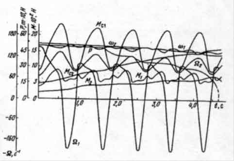
Figure 5 – The waveforms of drive parameters dvoprivodnogo scraper conveyor equipped with a fluid coupling is under Locking:Мс1, Мс2 – given to the turbine wheel hydraulic clutch moments of resistance of the main and tail drive, Нм;М1, М2 – hydrodynamic torque applied to the turbine wheel of the main and tail drive, Нм; Р – the maximum effort into scraper chains, Н; ω1, ω2 – motor angular velocity, sek-1; [5].
Feature of the fluid coupling is the low level of technology, due to the fact that its operation determines the long-term protection to stop the conveyor to the time needed to re-fill fluid couplings emulsion and installation of new safety smooth insertion (Figure 6).The intensity of the melting of inserts depends on the load of the conveyor, the fluid level in the fluid coupling, hydraulic clutches and the most quality inserts, and in some cases up to 3-4 times per shift.
Thus, the use of hydraulic couplings in conveyor drive be dependent work of the past and sewage treatment systems in general, the availability of fuse mine site. The absence of such forces service personnel to install instead of fuses steel bolts, ie to violate the requirements of conveyor operation. In this case, when reloading a second conveyor or triggered protection fluid coupling, or sifter overpressure torn, destroying, as a rule, the drive motor. This poses a risk of injuries people [4].
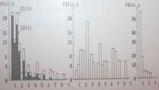
Figure 6 – Histograms mining sites downtime due to failures Conveyors: f1(t) – gusts scraper chains, including: f2(t) – impulses in the upper branch, f3(t) – impulses in the lower branch; f4(t) – of fuse fluid couplings (t, h.)
Design features a fluid coupling can judge that it is not only outdated and starting defensive tool because of the cumbersome work for installation and repair, low reliability, and as a consequence of short-life, but is not an effective means of start-up and protection of the scraper conveyor [4].
3. The goals and objectives of the study
The aim of the study is to increase the productivity of mining scraper conveyor by preventing impulse scraper chain for locking the study on the basis of the parameters of the structure and the technical implementation means quick protection against dynamic loads.
To achieve this goal should be solved the following problems:
- Performed an analytical review of research and technical solutions to the problems of ensuring trouble-free operation of mining scraper conveyors.
- Develop a mathematical model to study the processes drive the scraper conveyor for locking the information to determine the parameters to be used in the protective equipment.
- Justify the algorithm and develop a structural and fundamental means of automatic circuit protection scraper chain for locking of the gusts.
- To substantiate the requirements for safe and trouble-free operation of the developed automation tools.
4. Theoretical analysis of the properties of devices accelerated braking asynchronous motor
Specific operating conditions cause frequent pipeline locking him pulling unit, leading to a chain of impulses and calls for the establishment of appropriate protection. In this case, the protective device should not significantly complicate the design of the drive [2].
In connection with the above, practical interest is finding ways to identify the known properties of locking the drive belt:
- the intensity of the angular velocity of the engine;
- the intensity change of the current consumed by the motor.
The initial state of each of the braking process is the driving mode of the engine. An indication of the inhibitory process is the formation of the electromagnetic torque of the motor, the direction of which is opposite to the direction of the angular velocity of the motor shaft. One of the options to ensure the protection of the scraper conveyor of locking can be shutdown and subsequent inhibition of the drive.
The principle of induction-dynamic brake induction motor.
The effectiveness of the braking process asynchronous motor largely determined by the DC (rectified) current in the stator phases him. On the other hand, the magnitude of this current is determined by the voltage value supplied to the stator emf induced in the windings of the stator rotating field of the rotor currents. If emf in its polarity coincides with the polarity of applied voltage, its action will be directed to the decrease of the braking current. This potential difference will be determined by the instantaneous values of applied voltage and electromotive force of rotation and lead to a decrease in the intensity of braking. Thus, effective induction motor dynamic braking can occur in the absence of its stator windings reverse emf.
The efficiency of the induction-dynamic braking asynchronous motor is the elimination of this emf (at the beginning of the process of inhibition), which is accompanied by the creation of large amplitude pulses braking power. In the mining mode of induction-dynamic braking is used to stop the slow bremsbergovyh electric conveyor belts, emergency stop actuators other mining machines. The process of induction-dynamic braking force is created in the SCR circuit in the induction motor stator circuit as shown in Fig. 7 and involves alternating states of dynamic (DB) induction (IB) and, in fact, an induction–dynamic (IDB) engine braking.
Figure 7 – Design scheme of analysis of the study of the process of induction-dynamic braking asynchronous motor
(animation: 11 frames, 5 cycles of repeating, 24 kilobytes)
Injection current is created by applying to the stator through the thyristor VS1 и VS2 line voltage half UАВ network. The effect is created by the induction braking circuit via the thyristor VS3 EMF rotor AD:
eоб = (1/√3)pωb(L0(2Is(k+1) + Isk) + Lr(2Ir(k+1) + Irk)) , (4)
where p – number of pairs of asynchronous polyusіv dvigunov; Is; Ir – Stroomi i rotor stator; L0 – іnduktivnіst head magnіtnogo field rozrahunku per phase asynchronous dvigunov.
The process of induction-dynamic braking illustrated diagrams relevant parameters induction motor and the mains (Fig. 8). At intervals of dynamic braking and polarity UAB and eоб match. In this UAB > eоб. Home DG determined by the angle a unlocking thyristors VS1 and VS2,and the ending – the conduction angle of β. Braking current I is determined by the difference between the instantaneous values UAB and eоб.
IТrн + LнdIТ/dt = UAB - eоб(АВ) , (5)
where rн, Lн – general resistance and inductance leakage current brake. On the interval IT thyristor VS3 is conducting, whereas, thyristors VS1 and VS2 – not in the lead. The braking current IТ is determined by the instantaneous values of the motor EMF (eоб).
IТrн + LнdIТ/dt = |eоб(АВ)| , (6)
On each of the intervals of DT and IT emf of rotation is determined corresponding to its amplitude (Евр mi) and the initial phase (γ):
Eоб = I′Тr′Т((1 - s)/s) , (7)
eобi = Eобmi sin(ωbit + γ) , (8)
where ωbi = ω0(1 - s) – emf angular frequency corresponding to the i-th interval braking decreases, eventually down to zero. By decreasing the angular velocity of the induction motor decreases, the amplitude and frequency of its emf, and comes to the state where the polarity and UAB and eоб different from each other. In this case, thyristors VS1; VS2; VS3 be in the open position and the brake motor current IТ determined by the sum of the absolute values of instantaneous values UAB and eоб (range, IDT):
IТrн + LнdIТ/dt = UAB + |eоб(АВ)| , (9)
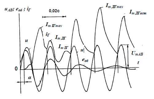
Figure 8 – Flow forming the stator current induction motor in the process of induction-dynamic braking
The expressions (1.52, 1.53, 1.56) are solved step by step in order of appearance with the characteristic intervals discussed above states braking. This takes into account the appropriate initial conditions, the magnitude and frequency of the emf induction motor. Their solution is the following expression:
Ir(t) = e-t/Tn(c + tk∫tn(U(t)/Lн)) e-t/Tn dt , (10)
where tn, tk – the beginning and end of the relevant braking intervalv, c = U(tн) / zн; Тн – time constant of the windings of the motor (Тн = Lн/rн).
If there is no current through the VS1 and VS2 current in the thyristor VS3 is determined by the self–induced emf induction motor:
Ir(t) = Ir(tni) e-t/Tn , (11)
wheare tni – the start of the above-mentioned i-th state;
Brake current is substantially independent of the angle α thyristor VS1; VS2. Its value determines the level of braking torque (МТ), which affects the intensity of the braking engine:
Mг = 2Ir2r21 / ω0Sнач , (12)
where ω0 and Sнач – respectively, synchronous speed of the rotor induction motor and slip at the beginning of the IMT.
Ir(t) = Irначe-t/Tn , (13)
where Irнач – the initial value of the braking current corresponding interval. At the end of fighting back emf induction motor is its braking current will be determined only by the leading of the thyristors VS1; VS2 with the angle α of the phase regulation [2].
Findings
Thus, the process of induction-dynamic braking asynchronous motor can get high blood pressure in the braking current mode is set by effectively suppressing emf, while in the process of suppression of emf for the initial surge current induction braking. Depending on the angles thyristor, the average intensity of braking power BP be within the range 0,3-6. This result makes the system an induction-dynamic braking BP admissible with respect to the drive mining machines.
References
- Чугреев Л. И. Динамика конвейеров с цепным тяговым органом / Л. И. Чугреев – М.: Недра, 1976. – 256 с.
- Маренич К. М. Автоматизований електропривод машин і установок шахт и рудників: навч. посібник для вузів [Під загальною редакцією К. М. Маренича] / К. М. Маренич, Ю. В. Товстик, В. В. Турупалов, С. В. Василець, І. Я. Лізан – Донецьк: ДонНТУ, Харків: УІПА, 2011. – 245 с.
- Маренич К. Н. Асинхронный электропривод горных машин с тиристорными коммутаторами / К. Н. Маренич – Донецк : ДонДТУ, 1997. – 64 с.
- Маренич К. Н. Асинхронный электропривод подземного скребкового конвейера с тиристорным пуско-защитным аппаратом [Дис. канд. техн. наук: 05.09.03] / К. Н. Маренич – Донецк., ДПИ, 1991. – 238с.
- Лаусенко А. В. Скребковые конвейеры. Справочник [Под ред. А. В. Леусенко] / А. В. Лаусенко – М.: Недра, 1992. – 221 с.
- Штокман И. Г. Расчёт и конструирование горных транспортных машин и комплексов: учебник [для студ. высших учебных заведений] под ред. И. Г. Штокмана. / И. Г. Штокман, П. М. Кондрахин, В. Н. Маценко и др. – М.: Недра, 1975. – 464 с.