Dynamic Vergence Control in Active Robotic Vision
Авторы: V. Riabchenko, Y. Ladyzhensky, A. Melnyk, V. Khomenko
Источник: Материалы конференции «Информационные управляющие системы и компьютерный мониторинг» ИУСиКМ - 2013, ДонНТУ, Донецк.
Авторы: V. Riabchenko, Y. Ladyzhensky, A. Melnyk, V. Khomenko
Источник: Материалы конференции «Информационные управляющие системы и компьютерный мониторинг» ИУСиКМ - 2013, ДонНТУ, Донецк.
V. Riabchenko, Y. Ladyzhensky, A. Melnyk, V. Khomenko. Dynamic Vergence Control in Active Robotic Vision. Methods of vergence control in robotic vision and disparity matching in computer vision are analyzed. The method of vergence control in binocular vision system that is based on an artificial neuronal network is implemented. Limitations of the system were revealed and improvements proposed.
active vision, stereo vision, dynamic vergence, disparity matching, robotics
In binocular systems a vergence is the simultaneous movement of both eyes in opposite directions to obtain or maintain single binocular vision [1]. This movement is needed to direct both eyes at the same gaze point. Such condition is evident for biological systems such as the human one because the vision acuity is not the same: it is higher at the fovea, and is lower at the periphery of the visual field. The controlled vergence also gives a lot of advantages to the artificial vision such as: simplification of formulation and solving the computer vision tasks, esthetics and ergonomics of humanoid robot interaction with a human.
This article describes a method of vergence control in the stereo vision that is based on disparity matching. Binocular disparity refers to the difference in image location of an object seen by the left and right eyes, resulting from the eyes' horizontal separation (parallax). The figure 1 presents a disparity problem with few corresponding points [2]. In the case of artificial vision, if both cameras are directed at the same object, then this object is projected on the center (analog of fovea) of their projective planes (analog of retina) and disparity is close to zero. If the object is projected in the center of one of the cameras and on the periphery of another, then the disparity is high and solution of stereo vision tasks is quite difficult.
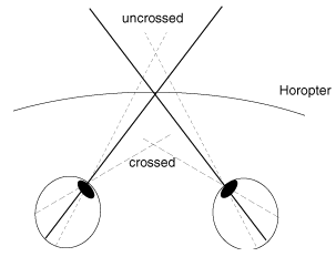
Figure 1 – Projections of disparity and corresponding points on eyes retinas or projective planes of cameras
The bibliographic analysis of different methods of vergence control as a part of an active vision system was carried out. We found that starting from the very first publications concerned to active vision, authors emphasize the importance of vergence control [3][4]. This control, by the analogy with biological vision systems, is often based on the disparity estimation. At the current state, we can distinguish two basic ways to estimate disparity or/and to locate of a pair of corresponding points on different cameras [5]:
The binocular system described in this article is based on algorithms and structure of the artificial neural network (ANN) proposed in [8].
The aim of this paper is to implement a system based on the ANN to solve the problem a vergence control. Based on disparity matching, the ANN produce the control signal to the motors of cameras (analogy to oculomotor muscles) in order to direct the view of cameras to a gaze point. The neural network does not need a computer based on Von Neumann architecture; it should fully take advantage of its mass parallelism to solve the task. This parallelism can be achieved using a cluster or a multicore processor.
The main research task is to implement a vergence control method in the active stereo vision described in [8] and to explore its preferences and drawbacks. Also, we aim to improve structure of the ANN and algorithms of its parallel realization. The work is realized within the scope of French-Ukrainian educational MASTER program (collaboration of the DonNTU and university of Cergy-Pontoise, France) [9], as a part of the master research project. Practical part of research is realized at the laboratory of control of electromechanical interactive systems of DonNTU (building 8, room 105A).
The goal of the proposed system is to adjust two cameras so that both of them has the same 3D point projected on the center of their image planes, like the human eyes look at the same spot when trying to assess the distance of a certain object. The following assumptions were made in the choice of the pixels to be compared with each other. [8]
We supposed to have a master(left) and a slave(right) camera. The images provided by these cameras will be referred to as master and slave images. The system adjusts the optical center of the right camera so that the same point P is projected on both of the optical centers, while the master camera is not moving at all. [8]
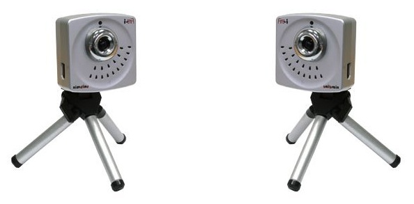
Figure 2 – Fire-i cameras used in experiments
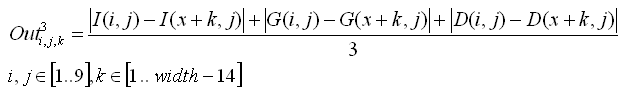
To solve the presented problem we use an ANN of a type “multilayer perceptron” without internal feedbacks. The neural network is built in a way to minimize the disparity by turning the slave camera. The ANN which is biologically inspired with 5 layers associates symbolic features of the images and aims to determine direction of the slave camera rotation. The symbolic features of a pixel with coordinates (x,y), are:
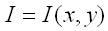
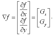
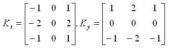
The figure 3 presents these three pixel properties which will be used as image features.
Figure 3 – Intensity (a), gradient magnitude (b) and gradient direction (c)
The ANN presented on the figure 4a has 5 layers, it does not contain feedbacks and needs no learning. The first layer is designed to input data from the regions of interest (ROI), a square 15*15 in the center of an image obtained from the master camera, and a band with size width*15 in the image obtained from the slave camera. As each pixel is characterized by three features (I, G, D) the first layer will contain 3*15*15 + 3* width*15 neurons. The outputs of first-laver neurons will intercross at the second level in the way showed on the figure 4b. The second level contains 15*15*(width–14) triplets of neurons, which compute module of difference between each of pixels feature (I, G, D).
Neurons of the third layer have three inputs each and realize the following function of similarity between a pixel from a leading image M(i, j) and a pixel from a slave image S(k+i, j):
Together, the second and third layers realize the pairwise comparison of pixels symbolic features. The multitude of neurons with a certain kn will realize a comparison of pixels from two windows 15*15: the main one and a kn-th window from the slave image [8].
![Figure 4 – General view of the ANN (a) and neurons of the second layer (b) [8]](images/article1_pic10.png)
Figure 4 – General view of the ANN (a) and neurons of the second layer (b) [8]
On the fourth layer, the k-th neuron calculate the degree of correlation between the window obtained from the center of the master camera image and the k-th window from the band of the slave camera image. Each neuron has 3*15*15 inputs, which values are summarized, with preliminary subtracting each of them from 255. As the result, if each k-th neuron has the maximum output value, then the k-th window corresponds to the image from the center of the master camera and it is necessary to turn the slave camera in a way that the image from k-th window will be in the center of a slave camera.
Cameras we used (which are presented on the figure 3) have a resolution of 640*480 pixels. That means that the central window has the number nc = 640 - 14 / 2 = 313. During the experiment, when the leading camera (right) watched at the left side of a sick vertical line, the slave camera (left) watched a little more to the right, the neuron number n=300 had a stable maximum output value. Output signals of the fourth layer neurons are presented on the figure 4.
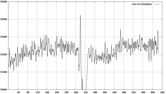
Figure 5 – The output values of the forth layer neurons
In order that two neurons of the 5-th layer could be used to control motors of the slave camera, the 4-th layer uses principle “the winner takes it all” (WTA). That means that only the winning neuron is activated. The 5-th layer has two neurons: one of them indicates the direction of the camera rotation and another indicates the value of rotation. Both neurons obtain input data from all neurons of the fourth layer (where only one is active). The input weights of the first neurons are negative at the left from the center and positive at the right. The weight of the center input is 0. Input weights of the second neuron are incremented by 1 when receding from the central connection.
We analyzed the methods of vergence control in computer vision for robots. The vergence control system based on ANN was implemented. As improvement we investigate the algorithm of window size dynamic control to achieve better results. Experimental results showed that the method is enough stable when optical axes of cameras lay in the sane plane (like for example in a visual systems of human, most of animals and robots).