

Summary on the theme of master's work Study of an adaptive detector of radio signals on the background of non-Gaussian noise in order to improve performance
Content
Introduction
1.Relevance of the topic
2.The purpose and objectives of the study
3.The main types of spread spectrum
3.1.The frequency modulated (FM) signals
3.2.Multifrequency (MF) signals
3.3.Phase-shift keyed (FM) signals
3.4.Discrete frequency (DF) signals
3.5.Discrete components of the frequency generator (RNG) signals
Findings
List of sources
Noise-like signals (NLS) are called such signals in which the product of the width of the spectrum F for the duration T is much greater than unity. This product is called the base of the signal, and is denoted by B, ie, B = FT.
At NLS B >> 1. Noise-like signals sometimes called complex as opposed to simple signals B = 1. Because the signals from the limited duration range has unlimited length, to determine the width of the spectrum using various methods and techniques. For real NLS consisting of a finite number of elements can always be uniquely identified and F, and B.
In spread spectrum communication systems with the spectral width of spread spectrum F is always much greater than the bandwidth of the transmitted message. In digital communication systems that transmit information in the form of binary symbols NLS duration, and speed information related cotnosheniem R T = 1 / R. Therefore, the base PNS B = F / R characterizes the expansion of the range of the spectrum relative to PNS posts. In an analog communication system in which the message is equal to the upper frequency of the frequency reference and W is 2W, B = F/2W.
And if B >> 1, the F >> R and F >> 2W. That's why communication system with NLS in foreign literature called communication system with advanced (or distributed) spectrum and in our literature - broadband communications systems.
System with noise-like signals (NLS) have been known for half a century. During this time, many of their issues are eliminated. In the current system due to the PNS are becoming more widespread. The process of expanding the areas of communication systems using spread spectrum and is irreversible in the near future, attention to them will increase.
The basis of the theory of spread spectrum communication systems laid by VA Kotelnikov [1] and Shannon [2], and based on code division - work DV Ageev [3]. According to the theory and technique of spread spectrum communication system written many books, articles, reviews, details of which up to 1981 can be found in books [4 - 9].
2. The purpose and objectives of the study
Purpose - to study the adaptive detector of radio signals. Requires an analysis of existing methods of detection, discover the essence of the method chosen, to identify the main features and characteristics of the detector is based on the method of pattern recognition and bring its advantages and disadvantages. In conclusion, you need to make a comprehensive analysis of the data and to evaluate the effectiveness of the method.
3. The main types of spread spectrum
A large number of different NLS, properties which are reflected, in many books and magazine articles. Common terminology does not exist yet. However, the spread spectrum can be divided into frequency modulated (FM) signals, multi-frequency (MF) Signals, phase-shift keyed (FM) signals (with the code phase modulation QPSK signals), discrete frequency (DF) signals (frequency modulation with a code - CFM signals FSK (FM) signals), discrete frequency components (DFS) (composite signals with frequency modulation code - SKCHM signals).
In parentheses are the other names. Sometimes referred to simply as FM signals NLS, DF signals - signals with frequency hopping.
3.1 Frequency modulated (FM) signals are continuous signals whose frequency varies according to a given law.
Fig. 2.12 and illustrated FM signal whose frequency varies according to the law of V-shaped f0 - F / 2 and f0 + F / 2, where f0 - center (carrier) frequency signal, F - the spectral width, in turn equal to frequency deviation F = Δfd. Duration of the signal is T. Fig. 2.12, b is a time-frequency (f, t) - a plane, which is approximately represented by hatching energy distribution FM - signal frequency and time. Base FM signal to determine (1.1)
The frequency modulated signals widely used in radar systems as a specific FM signal to create a matched filter on devices with surface acoustic waves (SAW). In communication systems need to have a lot of signals. Thus the need for rapid change of the switching signal and the generation and processing apparatus leads to the fact that the variation of the frequency becomes discrete. In this case, the FM signals pass to DF signals.
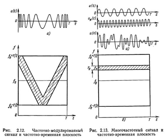
3.2 Multi-frequency (MF) signals (Figure 2.13, a) is the sum of N harmonics u1(t) ... uN(t), the amplitude and phase are determined in accordance with the laws of the formation of the signals. In the time-frequency plane (Fig. 2.13,6) patterned allocated one element of the energy distribution (harmonics) MF signal frequency fk. All the elements (all harmonics) completely cover the highlighted square with sides F and T. Base B signal equal to the area of the square. Spectral width of the element F ≈ 1 / T.Therefore, the base MF signal
ie equal to the number of harmonics. MF signals are continuous and for their generation and processing is difficult to adapt the methods of digital technology. In this drawback, they have also the following: a) they have a poor crest factor (see Fig. 2.13, a) and b) for the large base B is necessary to have a large number of frequency channels N. Therefore, MF signals no further rassmatrivayutcya.
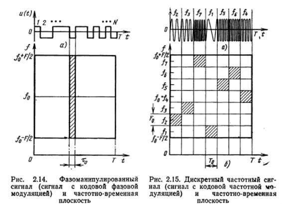
3.3 Shift Keying (PM) signals represent a sequence of radio pulses whose phases are changed by a given law. Typically phase takes two values (0 or π). Where in PM radio frequency signal corresponds to the video-FM signal (Fig. 2.14, a), consisting of positive and negative pulses. If the pulse number N, the duration of one pulse is equal to τ0 = T / N, and its width is approximately equal to the spectral width of the signal F = 1 / τ0 = N / T. In the time-frequency plane (Fig. 2.14 b) energy distribution patterned allocated one element (impulse) FM signal. All the elements overlap highlighted square sostorony F and T. Base PM signal
ie equal to the number of pulses in the signal.
Very promising are agreed filters charge-coupled device (CCD). according to published data using the matched filter CCD FM signals can be processed with the bases 10-2 ... 10-3 at durations of the signals 10-4... 10-1. Digital correlator on the CCD is able to base process signals 4·104.
It should be noted that the FM signals with large databases it is advisable to handle with the correlation (at BIS Ileana CCD). Thus B = 4·104 is marginal. But when using the correlation should first decide on an expedited sync acquisition.
Because FM signals allow wide use of digital methods and techniques of forming and processing, and these signals can be implemented with relatively large databases, the so · FM signals are one of the most promising types of NLS.
3.4 Discrete frequency (DF) signals represent a sequence of radio pulses (Fig. 2.15, a), the carrier frequencies of which vary according to a given law. Let the number of pulses in the signal DF M power, pulse duration is T0 = T / M, the width of the spectrum F0 = 1 / T0 = M / T. Above each pulse (Fig. 2.15, a) it contains the carrier frequency. At the time-frequency plane (Fig. 2.15, b) hatching marked squares in which energy is distributed impulsovDCh signal. As can be seen from Fig. 2.15 b, the energy DF signal is not evenly distributed in the time-frequency plane.
Base DF signals
since the base of the pulse F0T0 = 1. From (2.44) it follows that the main advantage of Discrete signals to produce the necessary base to the number of channels M = √ B, which is considerably less than for the MF signals. It is this fact that has caused attention to these signals and their use in communication systems. However, for large databases B = 10-4...10-1 Discrete signals are used only impractical as the number of frequency channels B = 102...103 that is excessively large.
3.5 Digital composite frequency generator (RNG) Discrete signals are signals that have replaced each impulse noise-like signal. Fig. 2.16, as shown videochastotny FM signal, parts of which are transmitted on different carrier frequencies, numbers of frequencies are above the FM signal. Fig. 2.16 b shows the time-frequency plane where the shading allocated energy distribution DFS signal. Fig.2.16, b Po structure not distinct from Fig. 2.15, b, but in Fig. 2.16, b Area F0T0 = N0 - Equal to the number of pulses in the FM signal odnoMFastotnom element DFS signal.
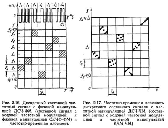
The number of pulses the full FM signal
Shown in Fig. 2.16 DFS signal contains as an element of the FM signals. Therefore, this signal is called for short DFS-FM signal. As elements of DFS signal mozhnovzyat Discrete signals. The energy distribution of the signal at the time-frequency plane is shown in Fig. 2.17. If the base element of Discrete Signal
then the base of the entire signal
Such a signal can abbreviate DFS-FM. The number of frequency channels in the DFS-FM signal is M0M. If the DF signal (see Figure 2.15) and the RNG-FM signal have the same base, and they have the same number of frequency channels. Therefore special advantages DFS-FM signal before signal DF has not. But the principles of the DFS-FM signal can be useful when building systems 6olshih Discrete signals.
Thus, the most promising PNS for communication systems are FM, DF, DFS-FM signals.
Findings
This master thesis is devoted to the actual scientific and technical objectives of the study of adaptive detector of radio signals on the background of non-Gaussian noise in order to improve performance, the basic requirement which is the accuracy of the receiving PNS.
- Котельников В. А. Теория потенциальной помехоустойчивости. - М.: Госэнергоиздат, 1956. - 150с
- Шеннон К. Математическая теория связи. - В кгн.: К. Шеннон. Работы по теории информации и кибернатике: Пер. с англ./Под ред. Р. Л. Добрушина, О. Б. Лупанова. - М.: ИЛ, 1963, с. 243-332
- Агеев Д. В. Основы теории линейной селекции. - Научно-технический сборник ЛЭИС, 1935, №10
- Варакин Л. Е. Теория сложных сигналов. - М.: Сов. радио, 1970. - 375 с.
- Варакин Л. Е. Теория систем сигналов. - М.: Сов. радио, 1978. - 304 с.
- Статистическая теория связи и ее практические приложения/Под ред. Б. Р. Левина. - М.: Связь, 1979. - 592 с.
- Диксон Р. К. Широкополосны системы: Пер. с англ./Под ред. В. И. Журавлева. - М.: Связь, 1969. - 592 с.
- Спилкер Дж. Цифровая спутниковая связь: Пер. с англ./Под ред. В. В. Маркова. - М.: Связь, 1969. - 592 с.
- Поляков П. Ф. Широкополосные аналоговые системы связи со сложными сигналами. - М.: Радио и связь, 1981. - 152 с.