
Abstract
Content
- Introduction
- 1 Analysis of existing structures rodless submersimble pumps
- 1.1 Analytical review of existing designs submersible pumps and spool valve-spool distribution of fluid in the hydraulic engine
- 1.2 Analytical review of existing designs rodless hydraulic drive submersible pumps with valve control
- 2 Rationale for work and selection design submersimble rodless hydravlic pump
- Conclusion
- References
Introduction
Relevance of the topic. Currently, due to the reduction of surface water resources, the use of groundwater for various purposes increases significantly, so the creation of high-pressure and high-performance equipment for pumping fluid from the wells is of great economic importance. The need for such technology for dewatering mines requires mining. Is also a great need to equip submersible dewatering wells drilled to drain deposits of underground resources and wetlands.
In our country and abroad used a lot of different technical means for artificial lift fluid designed for different operating conditions, which differ structurally and the principle of operation.
Their analysis shows that one of the most interesting and challenging lifts liquid is hydraulic piston submersible pumps, in one case placed the pump and hydraulic motor.
The possibility of using a liquid as a means for implementing the reciprocating movement in cars has long been known.In the Soviet Union the construction of hydraulic pumps begun in the late 30's engineer M.I. Martsishevskim In the 50 years of work on the construction of hydraulic pumps were concentrated in the Special Design Bureau of rodless pumps (OKBBN) and increased their volume. Especially great merit in creating domestic units owned by A.S. Cazacu, I.I. Rosina, L.G. Chicherova, G.I. Neudachina, V.I. Piliptsu [1].
Submersible pump is a hydraulic mechanism, a feature of which is that one the same amount of liquid to the same depth can be pumped at different flow rates and, accordingly, pressures of the working fluid.Conversely, if certain parameters of the pump power may be a different amount of liquid pumped from different depths. This is achieved by selecting the area ratio of the pistons pump and motor [2].
Submersible pump hydraulically actuated piston pump power ground (or other type of pump) pressure. With the help of ground-pump piston engine mechanical energy is converted into potential energy and kinetic energy of the fluid flow, which is on a power line goes to a submersible hydraulic piston pump and motor leads him into action, the energy of the liquid stream is converted back into mechanical. [3].
Feed submersible pump can be increased, without increasing the transverse dimensions of the mechanism. This is achieved by installing two or more pump cylinders. In particular unit 4-inch two-cylinder provides elevation 24.5 m 3 / h of liquid from a depth of 990 m for the same size parameters of all known types of water lift is much lower. When pumping from deep wells of small diameter hydraulic piston pumps are out of competition.
The operation setting does not affect the angle wells, allowing them to be used successfully designed and deviated wells.
Hydraulic piston pumps unlike rod successfully pumped liquid with a high content of impurities. This is made possible thanks to the hydraulic protection of the plunger pump to the working surface which is supplied under high pressure of the hydraulic fluid from the net, do not let the gap solids.
Some systems allow the use of lip seals rods and pistons that have a number of advantages over the slotted gaskets.
Hydraulic piston pumps differ from each other according to the type of the power cylinder and the pumping part, the type of control gear motor load distribution during the pistons up and down according to the method of delivery into the hole and flow of exhaust fluid from the wellbore and others.
Known hydraulic motors of submersible pumps with slide, valve and valve-spool distribution of fluid.
The most widely for pumping contaminated liquid from the wells have submersible pumps with hydraulic engines, having a valve distribution of fluid.
However, when pumping from wells contaminated liquids known hydraulic piston pump units found that the presence of the two valves in the hydraulic motor of the pump, which are interconnected not hard, difficult as they interact with one of the valves sticking, the engine stops and the pump unit has a pull to the surface for disassembly and cleaning of the hydraulic valve group. [4].
Purpose and objectives. Purpose – to improve the design of the hydraulic submersible pump with a valve capable of self-consolidation as it wears its working surface for pumping contaminated liquid from the depths of 1000 m or more of the small diameter wells with a low dynamic level.
To achieve this goal the following objectives are defined:
- Analysis of existing designs submersible pumps and hydraulic motors, valve spool distribution of fluid power.
- Improving the method of calculating the submersible pump with single valve hydraulic motor and the determination of its operating parameters.
- Improving the design of a submersible pump with single valve hydraulic motor.
- Development of technology for the use of advanced design with a single hydraulic pump hydraulic motor valve during pumping fluid out of the well.
Research methods. The problem is solved by compiling and analyzing patent and literature, theoretical studies of the research and development work.
Scientific novelty. The technique of calculation submersible pump with single valve hydraulic motor, which allowed to study the regularities of the improved device with a choice of an effective combination of structural dimensions of the mechanism and hydraulic parameters: hydraulic pump-well.
Scientific and practical significance of the results. The scientific value of the work lies in the possibility of using the theoretical model and the application of knowledge obtained in the drilling industry.
The practical value is in creating an efficient design of hydraulic pump with single valve hydraulic motor by providing coordination of the valve. Eliminate the possibility of jamming of the hydraulic valves particles of the solid phase when pumping highly contaminated liquids.
1 Analysis of existing structures rodless submersimble pumps
Deep hydraulic piston pumping unit is currently one of the three basic types of pumping equipment used in the world to operate the wells in the liquid minerals.
A characteristic feature is the use of volume hydraulic piston pumps for deep reciprocating motion, and energy supply units from the deep surface is continuously moving stream of fluid carrying the potential and kinetic energy.
A very valuable feature of the volume is its hydraulic capacity to transmit large amounts of energy from the flow of liquid having a relatively small expense, but high blood pressure. This feature allows you to create powerful units small size for small diameter wells.
It is advisable to emphasize that more flexibility with hydraulic systems, their ability to easily change their settings according to the time-varying parameters of targets for the oil industry and, in particular, for the operation of large producer is particularly important because it allows you to observe precisely optimum technological modes of operation wells throughout the period of their lives.
This effect is accompanied by the economic effect of reducing the capital cost of the repeated conversion of wells that have to produce with increasing flow rates watered out well exploited, for example, installations sucker rod pumps [5].
The distribution mechanism of the engine is the most important element of the hydro piston engines. Its main purpose is to change the direction of fluid flow, and therefore the distribution of forces acting on the moving system, in the points reversing piston. Another important function of the device is to regulate the speed of the pistons. Valves are set so that when approaching the extreme position the piston rod or by acting on them, they produce a permutation [6].
There are three main types of switchgear: spool, spool valves and valve-valve, which received the most widespread, but there are other systems with hydraulic motors reversing pistons (without valves and inkjet devices and crane).
The term valve-spool dispenser appeared in Yekaterinburg (Sverdlovsk) Mining Institute (GIS) due to the development of engine valves which combine the features of the valve and valve.
1.1 Analytical review of existing designs submersible pumps and spool valve-spool distribution of fluid in the hydraulic engine
In the well-known foreign designs only aggregates "Camco" Control in a certain approximation fits this definition: it switches to a slide, but the distribution element operates as a two-way poppet valve [7].
The disadvantage is the difficulty of setting a synchronous operation of the valves in the apparatus, which increases its cost for the manufacture.
In the department of hydraulic pump technology intelligence MD Yekaterinburg Mining Institute has an engine with a valve-spool distribution (figure 1.1).
Fluid is pumped from the surface to power the pump standpipe has constant access to the lower cylinder chamber 6 through the annular gap between the housing and the cylinder 7 through the window 10. If the spool 8 is in the upper position, the piston 9 by the pressure of the working fluid on its bottom surface will move upwards because the top of the cylinder 6 in this case is connected to the bore through the exhaust window, and the channel 11 in the piston rod. When the piston reaches the top position, slide your butt 8 abuts the stop 5 moves it up and compresses the spring 3. With a further rise of the piston spool will shift into neutral, characterized by the simultaneous overlapping windows exhaust.
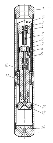
Figure 1.1 Submersible pump with a piston valve-spool hydraulic motor:
1 – upper head; 2 – cover; 3 – spring;
4 – housing limiter; 5 – the movable limiter; 6 – cylinder of the hydraulic; 7 – body; 8 – slide valve; 9 – piston hydraulic motor;
10 – window; 11 – stem bore; 12 – the discharge valve; 13 – bucket; 14 – foot valve.
This pressure in the upper cylinder chamber 6 will rise sharply. Due to the combined effect of the fluid pressure in the valve from the top of the cylinder 6 and the spring 3 it will be dead center position, the window will open and close the inlet exhaust window. The working fluid will have access to the top of the cylinder 6 and 8 extra spool moves to the lowest position. At the same intake ports are fully open, and the exhaust will be closed. Under the pressure of the working fluid on the upper cavity piston 9 is the entire system of moving parts move down. In the lower position of the piston valve member 8 lug abuts the fixed limit. Spool stops and further movement of the piston is moved to the neutral position, and then by the pressure of the liquid from the bottom of the cylinder and it will take up position. The top of the cylinder 6 is connected to the atmosphere. Begin another stroke up 9. This waste liquid from the top of the cylinder is expelled through the exhaust window, and the channel into the upper cavity pump where it is displaced from the wellbore with the pumped liquid.
Thus, the hydraulic piston 9 and the associated pump piston 13 will reciprocate movement. When the piston 13 upwards will suction fluid from the well to the bottom of the cylinder through a valve 14 and the injection of joint working and fluid from the top of the cylinder pump pumping pipe. When the piston 13 downwards it will displace fluid from the lower cylinder chamber via the valve 12 and the upper cavity and partially (in volume of the rod 11) in the pumping tube.
By pumping pipes mixed working and fluid will go to the surface of the settling system, of which a portion of the raised volume of fluid in the performance of the submersible pump can be spent for its intended purpose, and the other part in the amount required to drive the hydraulic motor, the power will go to the suction pump.
On the basis of the scheme were designed submersible pumps and multi-cylinder double-acting.
A disadvantage may be the jamming of the spool in a radial clearance, the reliability decreases structure.
Submersible water pump G.I. Neudachina and V.I Piliptsa (Figure 1.2) also has a valve-spool hydraulic fluid distribution system and soft seal seals and pistons that operate in abrasive applications[8].
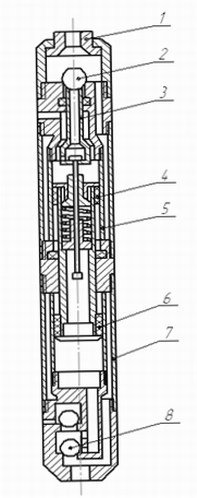
Figure 1.2 Hydraulic pump with valve-spool fluid distribution:
1 – emergency units rearrangement of valves, 2 – inlet valve of the hydraulic, 3 – valve, 4 – piston hydraulic motor,
5 – cylinder hydraulic motor, 6 – piston pump, 7 – the pump cylinder, 8.9 – suction and discharge valve of the pump.
Valve-spool assembly 2.3 fluid distribution is located in the top cover of the hydraulic cylinder piston 5 and 4 switches to its extreme positions. The design feature is the presence of a special unit 1, which allows in case of emergency stop of the hydraulic valve in the intermediate position to rearrange them in the end position without pulling the submersible unit on the surface. Pump capacity, with a diameter of 150 mm cylinder is 15 m3 / h with head up to 800m.
The hallmark of spool dispensers is the use of gap seals. Spool and sleeve in which they move, are on the mating surfaces of the different windows, the grooves, the grooves and grooves, repeatedly crossed in the process. In most systems, the cutoff is made closed fluid volumes requiring maintaining a certain pressure. It is these structural features for pumps with directional spool valve may be used only perfectly clean lubricating fluid [9].
A disadvantage of this design is the large area of the discharge valve, which makes operation of the valve spring.
1.2 Analytical review of existing designs rodless hydraulic drive submersible pumps with valve control
Submersible pump with G.I. Neudachina and A.G. Podkidysheva (Figure 1.3) has two fluid distribution valve and pump equipped with a dual action [10].
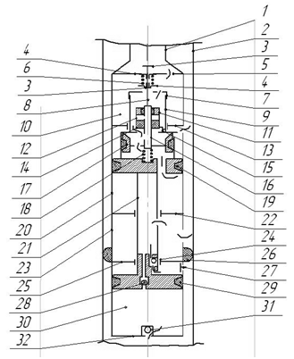
Figure 1.3 The submersible pump is double-acting hydraulic motor with a differential
The hydraulic motor consists of a pressure chamber 10 with lid 5, joined the power tube 1, the cylinder 20 with lids 13 and 22 provided with seals, hollow piston 19 with the plunger 9, supporting a glass rod 7 and 21. The valve consists of a dispensing device 8 with the traction lugs 3 and the hollow rod portion 16 carrying the springs 6 and washers 4, outlet valve 17 with a rubber sleeve, the inlet valve 15 with a piston 14 located in a glass 12 having a seal 11. Valve block rests on an auxiliary spring 18 which tends to move it in the upper position.
The pump consists of a cylinder 30 and lids 25 and 32, the piston 29 with the outlet ball valves 24 and 28, the suction poppet 27 and valve ball 31. The hydraulic motor and the pump are connected to the intermediate pipe 23. The cuff 26 and the tube 2 are used to lift the spent and fluid.
In the initial position the hydraulic fluid supplied to the tubes 1, pass under the open inlet valve 15 and the channel 19 in the piston to the lower cylinder chamber 20, outer chamber of which is the outlet. Under the pressure of the working fluid piston and all associated parts are moved to the top position. Since the exhaust valve 17 is pressed against the fluid pressure piston to the top cover 19, the valve rod and move upwards. At the approach to the upper extreme position the upper plate 4 rests on the cover 5 and 6 will cause compression of the spring. When the power of its compression exceeds the fluid pressure at the outlet valve 17, the valve unit will spread to the lower position, the inlet valve 15 is closed and the outlet 17 opens, further squeezing the auxiliary spring 18. Piston group moves down through the fluid pressure on the plunger 9.
At the lower end position support flap 7 abuts the cover 13 and a lower washer 4 depresses the spring 6. When the power of its compression exceeds the fluid pressure at the inlet valve 15, the valve unit will spread to its original position. Because of this fluid again access to the bottom of the cylinder 20, which at that time will be dissociated from the upper part of the exhaust. Begin another piston stroke up.
To reduce stress on the separation of the intake valve it has a discharge. It is achieved by the fact that the internal cavity 12 is filled cup through the passage at the bottom of rod 16 for spent liquid which is less than the working pressure. This can increase the cross section of the flow channel without increasing the stiffness of the spring 6. Furthermore, the housing cup 12 serves to protect the unit from the ram.
Unloading of the intake valve 15 allows the unstressed gate valve on the seat by means of the calibration channel 16 in traction, allows to limit the speed of liquid filling nozzle 12, and hence reduce the speed of the valve 6 under the action of spring.
Exhaust fluid from the hydraulic cylinder 20 is uniform in the gap between the power and the hoisting 1 2 pipes above the seal 26. At the stroke of the piston 19 is displaced upward by the piston, and on the downward stroke – the piston 9. balanced operation of the pump is achieved by the choice of usable area of the piston in accordance with the load. Reciprocation engine piston 19 is transmitted through the piston rod 21, the pump 29. The liquid from the wells alternately sucked into the upper or lower cavity of the pump cylinder 30 through valves 27 or 11 and is forced through the discharge valves 24 and 28 into the hollow rod 21, and then into the tube 23 and further to the lifting column 2.
Known reversible cylinder G.I. Neudachina to drive submersible pump piston differential action (Figure 1.4) consists of two valve seats which are made in the cylinder cover provided with holes for working fluid, a pusher cooperating with the distribution valve. Switching the valve piston is[11].
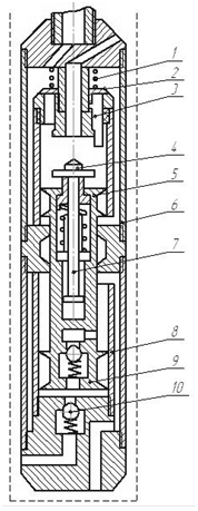
Figure 1.4 Reversible hydraulic cylinder:
1 – spring; 2 – inlet valve; 3 – pusher; 4 – exhaust valve;
5 – piston hydraulic motor; 6 – cylinder of the hydraulic; 7 – traction; 8 – suction valve; 9 – bucket; 10 – the discharge valve
A disadvantage of the design is the lack of protection from the action of exhaust valve speed pressure fluid can work only in strictly vertical wells, as the exhaust valve has a centering in the radial direction and moves with the piston.
2 Rationale for work and selection design submersimble rodless hydravlic pump
Using known two valve hydraulic motors requires a precise adjustment of the valve timing, it is difficult to perform a constructive way. Therefore, to improve the reliability of opening and closing valves, the hydraulic motor to perform appropriate one valve.
This will simplify the design concept and adds more reliability of the hydraulic actuator.
In order to address the shortcomings in the existing pumps designed pump unit with the valve hydraulic motor.
In the developed design of the hydraulic engine valve dispenser is made of the two sides, with the ability to commit to far from the piston position, spring-loaded balls.
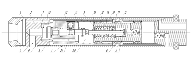
Figure 2.1 An improved one valve hydraulic motor
Figure 2.2 Animation showing the movement of the fluid in the hydraulic engine
(Animation: 5 frames, 7 cycles, 139 KB)
The engine comprises a housing 1 with a cover 2, in which a duct inlet 3 and outlet duct 4 of the working fluid, the piston rod 5 with 6. The cover 2 is formed with a chamber 7 seats 8 and 9, which are derived feeds 3 and supply fluid outlet 4. In chamber 7, the valve 10 is double-sided shank 11 fixed to the piston 5 farthest from the position by a spring-loaded ball 12. Shank 11 comprises a rod 13 with a head 14. In the rod 6 a spring 15 with the abutments 16 and 17. 5 piston divides the cavity of the housing 1 on rod end 18 with a window 19 and 20 rodless cavity, the latter being connected to the chamber 7 additional channel 21.
The working fluid flows through the channel under ¬ water through the window 3 and 19 in the rod end 18. The piston 5 moves up and displaces the liquid through the auxiliary channel 21, the chamber 7 and the discharge channel 4. With the approach of the piston 5 to the shank 11, the stop 16 cooperates with the latter. The valve 10 is set to the upper position, interacting with the valve seat 9. The working fluid now flows through the chamber 7 and the additional channel 21 in demon ¬ rod cavity 20. The piston 5 down and should end its stroke engages with the head 14 of the rod 13. The spring 15 dampens shock when interacting with the valve 10 piston 5.
When the piston 5 upwards towards the shank 11, the fluid enters the channel through the discharge assembly, the piston moves down, fluid flows into the suction unit and is fed through a hole in the lifting tube to the surface.
Thus, replacing the two valve mechanism on one valve, we have made simple types and greater reliability of the hydraulic actuator.
Conclusion
The developed design rodless submersible pump with hydraulic motor allows pumping from a depth of 990 m. with a small diameter wells, the water may contain contamination that will not affect the operation of the pump.
For reliable operation of the mechanism, the hydraulic motor has a single valve, mechanical seals are used, which greatly simplifies the design and ease of implementation of the hydraulic actuator, opening and closing the valve. At the same time provides high efficiency submersible pump in water with a high solids content.
The calculation of operating parameters of a submersible pump, which confirms the efficiency of the improved design. The technology and application of the rules of operation of the developed design.
Recently, increased production growth of drinking and industrial water for the needs of the population and industry. There is a tendency to an increase in the depth of wells and reduce their diameter. Therefore, this improved design will be useful, as it is simple in operation and maintenance repair.
References
- Пилипец В.И. Погружные насосы с гидроприводом: Учебное пособие /Пилипец В.И. v Донецк: ДонНТУ, 1998.
- Пилипец В.И. Насосы для подъема жидкости: Учебное пособие /В.И. Пилипец – Донецк: 2000. – 244 с.
- Анурьев В. И. Справочник конструктора-машиностроителя. В 3 т. /Анурьев В. И. – М : Машиностроение, 2001. – 864 с. ил.
- Казак А.С. Погружные бесштанговые насосы с гидроприводом. – Л.: Гостоптехиздат, 1961.
- Горгиджанян С.Н., Дягилев А.И. Погружные насосы для водоснабжения и водопонижения. – Л.: Машиностроение, 1968. дом «Вильямс», 2002. – 528 с.
- Неудачин Г.И., Пилипец В.И. Погружной бесштанговый насос для подъема воды из буровых скважин – М.: Гидротехника и мелиорация, №8, 1981.
- Богданов А.А. Погружные центробежные электронасосы. Гос-топтехиздат, 1957.
- Жуковский Н.Е. Прикладная механика. ГНТИ, 1931.
- Казак А.С, Росин И.П., ЧичеровЛ. Г. Некоторые итоги испытаний гидропоршневых бесштанговых насосов. «Нефт. хоз.», № 11, 1955.
- Казак А.С. Гидропоршневой глубинный насос для добычи нефти.Бюлл. научно-технической информации, № 39. ЦНИИТЭнефть, 1956.
- Казак А.С, Росин И.И. Результаты испытаний гидропоршневых глубинных насосов в 1956–1957 гг. «Нефт. хоз.», № 4, 1958.