
Drilling
The development of the shelf Black Sea and Sea of Azov – one of the key objectives pursued by the state. As has been pointed out by experts, the potential reserves of the shelf are estimated at 2.4 billion tons of standard coal. Ukraine is a net importer of hydrocarbon energy resources from other CIS countries, and it is economically viable energy independence with available stocks. It is therefore very relevant is the exploration of the shelf Black Sea, and as a consequence and the development of technical means for its implementation.
The master's work dedicated to research borehole layouts for sampling soil during drilling on the continental shelf, the development of structures and pile hydropercussion samplers for drilling in different hardness soils.
The National Programme for the development of mineral resources of Ukraine for the period up to 2030 and Development Strategy of Ukraine till 2030 is planned to increase the volume of oil and gas production on the shelf through the construction of new offshore production platforms. This is necessary that large amounts of geotechnical studies, including - geotechnical drilling wells up to 100 meters with specialized jackup drilling vessels and drilling platforms.
This requires the development of new and improvement of existing technologies and means of sampling of soils drilling of these wells.
In the Donetsk National Technical University in recent years, a number of technical means and technologies hydropercussion drilling geotechnical boreholes, which can significantly improve the technical and economic performance of drilling operations. Based on previous research, a further development of downhole samplers for geotechnical boreholes, namely precast and hydraulic hammers, on the basis of which is planned to improve technology and equipment used for drilling geotechnical holes a depth of 100 meters with a specialized drill ships and jack-up drilling platforms. At the same issues are important enough to the rational selection of layouts sampler with a drill string and determining their influence on the ROP.
The results will improve the performance and reduce the cost of drilling for geotechnical studies on the shelf.
Therefore, the development of new techniques for drilling wells on the shelf today is the actual problem.
Purpose – to improve downhole sampler percussion with hydraulic drive (driven piles and hydraulic hammers) for drilling offshore and definition of rational layout sampler with a drill string.
The main objectives of the study:
The object of study: hydroshock downhole hammer and percussion sampler with a hydraulic drive for drilling offshore.
Subject of study: workflows while drilling offshore precast downhole samplers.
As part of the master's work is planned to obtain relevant scientific results in the following areas:
The value of the work is to determine the effect of the design concept of downhole sampler percussion with hydraulic drive and link it with the drill string to the ROP and the justification of its design Layout parameters and for different conditions of use.
The area offshore drilling is actively developed, so there are a number of samplers developed counterparts. Currently Scheme G. Neudachina developed and widely used installation UGVP-150-130 UGVP, UGVP-130/8, UGVP-150M, capable of performing drilling odnoreysovoe out across vertical section of ground wells any consistency, related to I-IV categories by drilling capacity to a depth of 6 - 10 m from the board of specialized courts. Higher operational and technical capabilities of systems UGVP-150-130 UGVP implemented mainly by expanding the functions hydropercussion drill. In the developed multi-functional drill, except compulsory dives core set into the ground and create a liquid return to the core tube, possible to scour the walls of the wells along the surface of the core set. This creates the conditions in which immersion and removing the PBS produced no significant effect of friction forces on the surface of contact with the rock coring kit.
The apparatus used UMB-130 multi-function hydraulic hammers the drill starting with the top unit (VPU) to run the hydraulic hammer and a lower starting unit (NPU) to start jetting erosion.
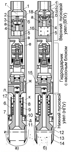
Figure 1 – Downhole samplers with hydraulic drive UMB-130: a) mode hydrowashout b) sampling.
CPG is placed in a cylinder 16 connected to the top adapter 1, and includes a trigger valve 3 with a spring 4 and a piston 2 with a spring 5.
NPU is connected to the anvil rod 15 17. The lower part of the stem has a stepped shape. The upper stage 10 provides a seal inner surface of the outer tube 12 and the lower step 11 is a sealing sleeve for the inner (core lifter) of the tube 13. On rod 17 concentrically mounted with the piston 8 and spring 9 starting valve 6, based on the spring 7, channels arranged in the upper sealing stage 10.
In the hydrowashout passed earlier wellbore launches the CPG. Increase the flow rate on the discharge. Due to this effect increases the dynamic pressure and differential pressure on the trigger valve 3 which moves downward, compressing the spring 2, and closes the axial hole "a" spring loaded piston seat 4 (Fig. 2a). The chamber "d" dramatically increases the pressure, which provides offset piston 4 down. This opens the window side "b" providing a fluid passage into the annular clearance "e" between the casing and the casing hydraulic hammers, bypassing the working chambers of the hydraulic machine.
The flow of fluid through the channel of "g" falls into the camera, "to", and fully accepted the surface of the valve 6 NPU, which overcoming the resistance of the spring 7 moves down, closing the channels "D" at the upper stage 10 the rod 17. Due to the increased in the chamber "to" pressure piston 8 moves along the rod, opening channels "L" for the passage of fluid in the core tube 13, and further, through a special core catcher in the pad 14 - Bottom hole.
To work BSS mode core sampling (Fig. 2b), in the discharge line is cleared ball 5. After planting the ball into the seat piston 4 on the discharge pressure increases, the force which provides a cut of 2 cotter pins. The piston moves down, blocking the channel "b." At the same time open the window "in" through which fluid is directed into the cylinder hydraulic hammers. Under the pressure of the liquid piston begins to perform back-and-forth motion between the anvil-tions with the transfer of impact loads on them, facilitate the introduction of RBM in the breed. Returning to the starting position CPG (Fig. 2a) only after getting the installation to retrieve the ball and recharging unit.
The development of offshore oil and gas fields Ukrainian contributed to the creation of new technologies and means of drilling during the geotechnical investigations at the sites setting platforms and tracks underwater pipelines. Studies carried out by specialists of the Department "Technology and engineering exploration work" Donetsk National Technical University with the participation of JSC "Company" Yugovostokgaz " allowed to develop the technology interval standardized drilling deep geotechnical boreholes with submersible hydropercussion projectiles [1] [2] .
In autumn 2007, a geotechnical studies Subbotinskom oil and gas field, which is being developed "Chernomorneftegas" with jack-up rig (SPBU) "Siwash" with the use of this technology has been drilled geotechnical boreholes depth 78 m
For the sampling of sediment in the sand and sandy soils used modernized Hydroshock drilling shells PBS-110 with the core barrel diameter 108 mm, and for the selection of monoliths - specially designed for this purpose pressed into samplers.
Technological scheme interval standardized making holes hydropercussion projectiles PBS-110 SPBU "Siwash" is shown in Fig. 1.

Figure 2 – Technological scheme interval standardized sinking wells with SPBU "Siwash" with PBS-110:
1 - swivel-oil seal, 2 - casing head ∅ 146 mm, 3 - clamp, 4 - casing head ∅ 219-245 mm; 5 - drill pipe∅73 mm, 6 - casing string ∅ 146 mm, 7 - PBS-110, 8 - core; Q - flow of a liquid.
First with the jack-up rig down riser diameter of 219-245 mm. Its bottom is installed at a distance of 1.5-2 m from the seabed. In the presence of strong currents down the column should bury in the ground to prevent it from vibration and bending for the work. Then down the casing pipe diameter 146 mm, designed for wall mounting hole in her uglubki. Thereafter, the sampling.
First shown in the first test with PBS. Before collecting the next sample blur breed unleashed the first interval, and then produce sampling. Switching modes is carried out by switching centers, forming part of the projectile. All subsequent intervals being tested similarly. Additionally provides for periodic mount borehole casing diameter of 146 mm as it uglubki by an amount one corresponding to the length of casing.
In 2006, the Donetsk National Technical University on the basis of pre-existing shells PBS-108 and PBS-127 were developed Hydroshock drilling shells PBS-110 and PBS-130 (Fig. 3) with a single column pipes with diameters of 108 and 127 mm.
Figure 3 – Schematic diagram of the shells PBS-110 and PBS-130: a) mode hydrowashout b) in the mode of core sampling.
Structurally, the shell consists of an upper part of the start-up(VPU), hydraulic hammer and the lower part of the start-up (NPU).
NPU includes a thick-walled cylinder 9 that connects to the bottom of the anvil 15. Placed on the rod 8 with the spring7 piston 6.
In the hydrowashout (figure 2. A) through the channel "g" goes an increased flow rate, leading to increased pressure on the piston 6, that is, overcoming the resistance of the spring 7 is displaced downward. Sequentially closing the windows "d" and the opening side windows "l" in stock 8. In this position, the elements NPU fluid flows inside the core barrel 10 and then through the shoe 11 and a special pass 12 core catcher, Bottom hole.
When operating hydraulic hammer mode core sampling (Fig. 2b) in the discharge hose was heading a ball. CPG is triggered, which provided the launch hydropercussion mechanism. From that moment began coring at the next interval of the well. The spent fluid flows through the annular gap between the casing and the casing hydraulic hammer, and through the channel "g" in the anvil 15 and the radial window "e" in the cylinder 9 leads to the well. At the same time, acting on the piston 6 strength, determined by the magnitude of the differential pressure of the fluid in the chamber "to" offset spring 7.
In 2007, the landfall of the Odessa gas field in the Black Sea performed experimental evaluation of the QSP-130. The shells were tested as part of the SBA-130 MB "Centaurus" at mnogoreysovom drilling of four wells to a depth of 8-10 m.
The prototype pile sampler is proboobtornik (Declaration patent of Ukraine № 51070 cl. E 21 B 25/18, publ. 15.11.2002) which contains a piston motor and a striking assembly of the hammer, anvil and the housing is rigidly connected to the core tube.
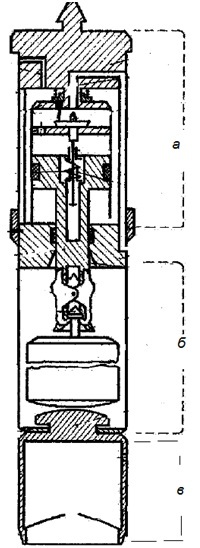
Figure 4 – Sampler percussions: a) the hydraulic motor, b) percussive unit, c) core barrel
In this case, the piston rod of hydraulic motor is separate from the striker and it is fitted grips for periodic interaction with striker and the partition separating the hydraulic motor from the impact site on the striker and the partition made ??conical surfaces and anvil and Core Lifter movably mounted relative to the housing assembly impact.
Soil sampling is performed as follows. In operation, the hydraulic motor seizures reciprocating motion. In the lower position they lock the striker, which is on the anvil. With the rise to the level where the interaction is captured with a partition the firing pin is released and moves down under its own weight to the anvil and does score a hit. Under the influence of shock transmitted to the core tube, there is a recess in its bottom. After the end of the voyage sampler is removed from the well sudnovoy winch.
This sampler has a drawback. Its design does not provide a flush bottom of the well through the cavity core tube, since the system of channels for the circulation of fluid in the sampling does not allow it. Thus, when using sampling in mnogoreysovom drilling technology, when it descends into the well on drill pipe, rather than within them, before collecting soil samples can not be cleaned from the slaughter of chipped rock which leads to a reduction of the actual length of the flight and the quality of the sample.
We developed unique devices can distinguish a number of major drawbacks:
In advanced designs of these factors minimized, because they have a relatively simple construction, easy maintenance, have a distribution unit to redirect the flow of fluid to wash the face.
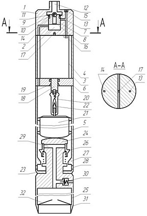
Figure – Downhole samplers percussions with hydraulic drive
The sampler consists of three main components (Fig. 4) – piston hydraulic motor (DG), stroke unit (the firing pin housing, anvil) and the core tube.
The sampler operates in the following manner. It is lowered into the well on a drill string to which it is attached to the adapter. Upon contact with the shoe slaughter descent ends.
Prior to sampling of the cleaning face chipped rock the drill string supplied liquid. It chamber 2 through the channels 8 and 14, an annular gap between the casing 3 and the body 4 enters the cavity of the body 5 impactor assembly from the annular space between the valve spool 26, and seat 27 is fed through hole 28 into the annulus between the borehole wall and sampler .
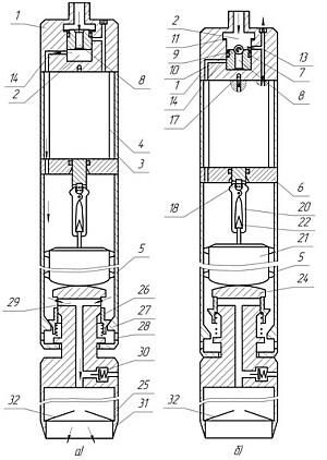
Figure 6 – Downhole samplers percussions with hydraulic drive operating position: a) washout the borehole bottom, b) core sampling
When lifting the probe over the slaughter reduced the gap between the valve spool-26 and seat 27. As a result, the pressure above the valve spool 26 increases, and the latter to compress the spring moves downwards and opens the channel 29. Fluid through the channel 29 enters the cavity core tube 25 and then - through the core catcher 32 and the shoe 31 - on the bottom of the well, blurring showered with rocks. (Fig. 5a).
For sampling in the drill string is reset starting valve 10 (the ball), which sits in the seat 9 and closes the axial channel 8 piston 7. The pressure in the dispensing chamber 2 increases the adapter 1, the pins 11 are cut, and the piston 7 is moved to the lowermost position. This channel 14 overlaps a side surface of the piston 7 and the channel 13 opens. Thus, the cavity of the body 5 is separated from the pressure source and the fluid enters the inlet of the hydraulic cavity 16 which comes into operation. In operation, the stem 18 carries out reciprocating movement, and hydraulic fluid exits from the well through the passage 17 (Fig. 5b).
When the rod 18 upwards, he captures 20 raises the firing pin 21 of the anvil 24 to 20 seizures contact with the tapered surface 19 of the partition 6. Thus the striker 21 is released, and under its own weight moves downwards and strikes the anvil 24. Under the influence of this blow Core Lifter deepens into the ground. When the rod 18 down clamps 20 are recombined with a conical head 22 of the striker 21. After this cycle is repeated. After the end of the voyage sampler is extracted from wells winch.
The advantage of this is the ability to pile sampler flushing the well bottom and erosion chipped rocks before assaying, which improves the quality of the soil samples.
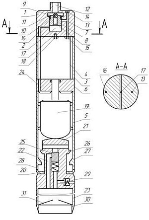
Figure 7 – Downhole samplers with hydraulic drive
Core barrels refers to the technical means of drilling wells and can be used for the sampling of soils neskalnyh in soft sediments.
Core barrels works as follows. It is lowered into the well on a drill string (not shown), which joins the adapter 1. After contact shoe 30 and the well bottom slope ends.
Prior to sampling downhole cleaning of rock, which showered, the drill string is supplied liquid (Fig. 7 a). Flushing fluid through the channels 12 and 8 into the distribution chamber 2, the passage 16 on the adapter 1, the annulus between the casing 3 and the body 4, the passage 24 in the upper anvil 6 enters the cavity casing 5 impactor assembly from the annular space between the annular 26 and valve seat 27 through the opening 28 in the adapter 20 is fed into the annular gap between the walls of the wellbore and the sampler.
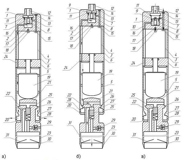
Figure 8 – Downhole samplers s with hydraulic drive in the operating position: a) When the projectile to the bottom of the well, b) washout the borehole bottom, c)core sampling .
When lifting the projectile over slaughter (Fig. 7b) an annular valve seat 26 is lowered to 27, whereby the pressure increases on the piston 25, compressing the spring which opens the duct 22 for passage of liquid in the tube core 23. Fluid through the core catcher 31 and shoe 30 is supplied to the well bottom, eroding the rock that crumbled.
For the selection of the sample (Fig. 7c) shell is lowered onto the bottom of the well. In a drill string (not shown) reset trigger valve 10 (bead), which sits in the seat 9 and the axial channel 8 overlaps the spool sleeve 7. The pressure in the distribution chamber 2 adapters 1 increases, the pins 11 are cut, the spool sleeve 7 is moved to the lowest position. This channel 16 overlaps the side surface of the spool sleeve 7 and the channel 13 opens. Thus, the cavity of the body 5 is separated from the pressure source and fluid flows into the inlet cavity 15, hydraulic hammers, which is actuated. In operation, the striker 19 reciprocates motion, striking the anvil 21 and the anvil top 6, and the liquid from the outlet chamber 18 is in hydraulic hammers through the passage hole 17.
Under the impact of the anvil 21 core barrel 23 deep into the ground, coming into its cavity, pressing the side lobes core catcher 31. Fluid from the core barrel 23 is forced into the borehole via a check valve 29. When you hit up the top of the anvil tube core does not take shock loads. Therefore, even with the rise of the hydraulic hammer slaughter tube core does not lose contact with the slaughter, which has a positive impact on the quality of the core. Due to the fact that strikes down only perceives the core barrel with an anvil, not the entire column-shell also increases uglubke a single hit and as a result - ROP.
After the end of the voyage the fluid supply to the Core barrels stopped. The drill string is raised extracting core barrel 23 with a shoe 30. In this case 31 holds the core catcher in the core barrel 23 sample.
Use of the proposed core shell allows for improving the quality of the soil samples at the expense of the core barrel constant contact with the borehole bottom. Strikes down only accepts core barrel with an anvil, not the entire column-shell, so also increases the deepening of a single hit, and as a consequence - ROP.

Figure 9 – Operation coring shell in the sampling mode
Under the impact of the anvil 21 core barrel 23 deep into the ground, coming into its cavity, pressing the side lobes core catcher 31. Fluid from the core barrel 23 is forced into the borehole via a check valve 29. When you hit up the top of the anvil tube core does not take shock loads. Therefore, even with the rise of the hydraulic hammer slaughter tube core does not lose contact with the slaughter, which has a positive impact on the quality of the core. Due to the fact that strikes down only perceives the core barrel with an anvil, not the entire column-shell also increases uglubke a single hit and as a result - ROP.
After the end of the voyage the fluid supply to the Core barrels stopped. The drill string is raised extracting core barrel 23 with a shoe 30. In this case 31 holds the core catcher in the core barrel 23 sample.
Use of the proposed coring shell allows for improving the quality of the soil samples at the expense of the core barrel constant contact with the borehole bottom. Strikes down only accepts core barrel with an anvil, not the entire column-shell, so also increases the deepening of a single hit, and as a consequence - penetration rate.
Master's thesis is devoted to the actual problem, because Ukraine needs to perform large amounts of geotechnical studies, including - geotechnical drilling wells up to 100 meters with a specialized drill ships and jack-up drilling platforms, for the development of the Black and Azov Seas.
In the course of the master's work is planned computer simulation uglubki in Soft Soil for a variety of arrangements of driven piles and hydropercussion samplers and analyze the data. Just to prove the design parameters of downhole samplers, perform a 3D-modeling and working drawings developed samplers.
When writing this essay master's work is not yet complete. Final completion: January 2014. Full text of the work and materials on the topic can be obtained from the author or his manager after that date.