
Abstract
Content
- Introduction
- 1. Relevance of the topic
- 2. The purpose of developing and tasks.
- 3. Analytical review of the analogues of the developed device.
- 4. The developed mechanism.
- Conclusion
- References
Introduction
Sampling of coal and host rock is an important component of any drilling exploration wells, but new tools for the selection of the samples, at the moment, is not created.
It is believed that technological shells started earlier, in full satisfy all the needs of the industry. The long period of development of new techniques in the CIS countries were not conducted.
The need for a modern exploration drilling in the modern technological tools, gradually began to leave in the first place. More and more scientific research institutes thawing its development and tries to make up for lost time.
West (Canada, USA) and East (China) on the contrary tried, what would this line of research and production related equipment not kept pace with the main areas. Are being developed as new technology, so the new technology for the selection of high-quality samples to the extent necessary.
The aim of this work is an attempt on the basis of previous results, get a new technical means for sampling rocks in complex geological conditions, as you can more effectively.
1. Relevance of the topic
Coring in unstable rocks, the double core barrels. These shells separated by ejector and ejector.
Dual core barrels are performed with a rotating and non-rotating inner tube and generally are of two types of DES-B and DES -H.
The principle of sampling in such a projectile is: well are simple single-core barrel, and in the depth interval of interest to us is a change of the projectile to a special (Dual Core barrels) further sampling is conducted with a reduced value of the basic parameters of the drilling mode.
The most effective coring in unstable rocks show shells that implement the backwash in the selection of weak-breed. Backwash is created using an ejector pump embedded in the technological tool.
The theme of this thesis is to create a dual-core-shell ejector, the sampling of coal and host parody by backwashing. At the core of the work is previously designed hardware EKS-P.
2. The purpose of developing and tasks
Objective: To develop a new technical tool for core drilling in unstable rocks to make a comparative analysis of the calculation of an ejector pump in two different methods.
In the course of the master's work is necessary to solve the following problems:
1. To analyze the existing technical means for coring in unstable rocks. Determine the optimum design.
2. Develop design of technical means in accordance with the specified parameters and dimensions.
3. To calculate the ejection site, or receive, specifications and dimensions.
4. Perform a comparative analysis of the calculated parameters by methods used in the department TTGR and methodology used in the mining department..
Methods of research - a compilation of information on previously developed devices, conducting mathematical calculations.
3. Analytical review of the analogues of the developed device.
Analogs of the developed tools are tube type DES and DES-H-B. The shells of this type are widely used in drilling in unstable fractured rock.
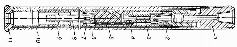
Figure 3.1 – Ejector projectile DES-V
To create a backwash when drilling in rocks interbedded in hardness, which is often seen shimming core, due to its selective attrition in some of the double tube core integrated ejector pumps.
Ejector Tank shells (ECS) are simple in design, so developed not only in the design institutes, but also in theme parties exploration expeditions.
The figure 3.1 shows a schematic of a dual shell ejector DES-In oburivayuschego type with a rotating inner tube design TsNIGRI.
The main element of the shell is the jet pump (ejector) consisting of a nozzle 2, the mixing chamber 3 (reception chamber) and the diffuser 4.
The pump energy is transferred to the worker thread with a large supply of energy to sucks (ejected) flow with a smaller amount of energy.
Work mud flow through the adapter comes in at 1-warren 2 with an opening 8-12 mm. Tapering to attachment 2, the flow rate increases to 30 m / s.
Cone of the nozzle hydraulic fluid enters the mixing chamber 3 and gradually expanding further into the diffuser 4.
A side channel adapter 5 fluid exits the space between the outer tube 9 and the inner tube 6 and enters the annular space.
This stream is divided into two streams - one directed upward,of at the expense of working, and the other - the downward equal to the flow rate ejected stream that washes the crown 11 and goes into the gap between the core and the inner core barrel 6.
The motion flow is ejected for the following reason: coming out of the opening two jet nozzles at the beginning of its formation consists of an inner region - a tapered core and the outer region, expanding the boundary layer. Subsequently, the core disappears and all the jet stream consists only of the boundary layer.
The boundary layer is a vortex shell suction inward particles surrounding fluid or air and carries them in his movement.
Due to this pressure in the mixing chamber is sharply reduced by the amount of ram workflow, ie creates a depression (depression). Therefore, in the chamber 3 through the suction holes adapter 5nachinaet ejection flow (drain) of the liquid inside the core barrel 10 via a slurry pipe 8, the pipe socket 7 and 6.
Thus, the kinetic energy is transferred to the workflow partially ejected flow.
In the mixing chamber 3 the liquid jets are mixed and fed into the diffuser 4, which is a converter of kinetic energy into the energy of the total flow pressure. A thread is created, directed upwards and provides backwash and increase core recovery.
The ratio of operating expenses and ejected flows is called the ejection.
Jamming of the core in the tube is due to its capture particulate slurry at the end of the flight to reduce the flushing liquid to 10-15 L / min.
In this case, stop leak fluid ejector pump. Rock particles are deposited in the gap between the tube and the core and wedge it. [1]
On gold deposits in Central Asia and Ukraine used shell ejector DES-N with a non-rotating inner tube design KazIMSa.
Such double tubes give a high core recovery in diamond drilling in hard fractured rocks through the creation of stable upward flow in the inner core tube.
The downside is the small shells ejecting length Flight 1 - 1.8 m due to the reduction of fluid resorbed as you fill the pipe until the end of the flow.
For drilling a small diameter with a small supply (30-40 l / min) at the Institute KazIMS designed ejector shells whose crowns with special rings and the outer surface of the pipe rising flow in the space between the pipe and the borehole wall to create a permanent hydraulic resistance providing stable during the upward flow inside the core tube.[1]
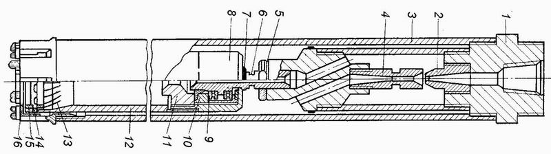
Figure 3.2 – Ejector projectile DES-N
I - adapter, 2 - nozzle, 3 - outer tube, 4 - Diffuser, 5 - lock nut;
6 - basic screw 7 - sealing lip, 8 - bearing housing;
9 - ball bearings 10 - ring: 11 - gland nuts; 12 - inner tube, 13 - Flap core holder;
14 - the case of core holder, 15-ring, 16 - carbide crown
4. The developed mechanism.
During the drilling data then ejected shell, pulling from the core pipe 21 small drill core, rises up the central tube 14 and through the radial passage 12 is in the chip catcher. At the outlet of the radial hole of the core material fine particles by the centrifugal force thrown towards the wall of the chip catcher and settle downward and the liquid freed from the core material, through the upper passage groove enters the ejector pump.
To remove the core and the core material unscrew the drill bit and core tube with chip catcher pulled out of the shell. After that weaken the locking screw 17 is separated from the chip catcher core lifter and recovered separately core and core material. Freed from the core and the core material of core tube and connect the chip catcher, fix the locking screw is inserted into the shell is screwed crown - and the shell is ready. Device is shown in Figure 4.1.
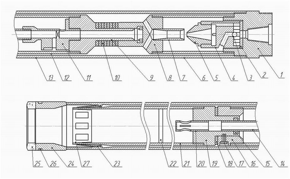
Figure 4.1 – Double column-projectile ejector EKS-P
The device consists of three adapters 1, 16, 19; distribution liner 2 and the driven distribution branch 4 which covers throw off the surface of the ball 3. Auxiliary channel to the distribution insert 5 2 connected nozzle, which produces a pressure drop in the mixing chamber and is entrained in the flow diffuser attached to the camshaft 7, the adapter 8, wherein the headgear is 9. In the distribution section of the adapter inserted rubber gaskets. Below is a chip catcher 11.12 which forms the outer tube 13, the collecting chamber sludge.
Kern enters through the crown 24 to the internal front pipe 21 to the stop 22. When removing the tube to the surface of the inner tube rises and stretches first, releasing kernoderzhatelnye sector 23, which capture and keep from falling of the core back to the slaughter (Fig 4.2).
Figure 4.2 – Movement through the tube core
(Animation: 5 frames, 7 cycles, 164 KB)
When fence core is deformed to narrow strip 10, which allows to reduce the mechanical impact on the core by contraction of the inner tube. The filter 20 is inserted into the adapter 19 has at the lower end cap and the sides of the hole 4, this reduces the hydraulic effect on the core of the fluid flow line when rinsing [4].
Findings
The development of new approaches to solve old problems and improvement of existing sampling device is weak fractured rock can store all the advantages and eliminate some of the disadvantages of the previously developed devices, which saves material funds. In a financial deficit, a way of solving problems with the introduction of the new equipment is preferred, since the development of new technological solutions and resource-consuming process.
With the improvement of the double shell ejector ECS introduces a new me-chanism for higher quality capture and retention of core, were also reduced the load on the core from the upper end of the core tube.
Having chip catcher enables cleaning solution inside the drill, thereby preventing zashlamovanie inner holes of small diameter.
The device allows you to make a qualitative leap in the coring compared with single pipes and increases the yield of the core compared to the dual pipes of similar design.
References
- Пилипец В.И. Бурение скважин и добыча полезных ископаемых. – Донецк, ООО «Типография «Новый мир» 2010.– 760 с
- Методичні вказівки до курсового проектування буріння свердловин на тверді корисні копалини/ А.С. Юшков.– Донецьк, ДоНТУ, 2008.–23с.
- Правила безопасности при геологоразведочных работах и бурении скважин технического значения / Госгортехнадзор Украины; Госкомитет Украины по угольной промышленности. – Донецк, 1993.-147с.
- Гребенюк А. А. Техника и технология получения керна. – М.: Недра, 1973
- Соколов Е. Я., Зингер Н. М. Струйные аппараты.–3-e изд., перераб,.–М:. Энергоатомиздат, 1989.–352 с.: ил.
- Воздвиженский Б. И., Волков С. А., Волков А. С. Колонковое бурение. Учебное пособие для вузов.–М.; Недра, 1982. 360с.
- Ганджумян Р. А., Калинин А. Г., Сердюк Н. И. Расчеты в бурении/Справочное пособие/ Подредакцией А. Г. Калинина, - М: РГГРУ,2007.–668 стр.