Аннотация
Bagordo О.G., Cazzulani G., Resta F., Ripamonti F. - A modal disturbance estimator for vibration suppression in nonlinear flexible structures. This paper presents a control strategy for the suppression of vibration due to unknown disturbance forces in large, nonlinear flexible structures. The control action proposed, based on the modal approach, consists of two contributions. The first is the well-known Independent Modal-Space Control, which increases system damping and improves its behavior close to the resonance frequencies. The second is a disturbance estimator, which calculates the modal components of the external forces acting on the system and compensates for them using actuator forces. The system modal coordinates, required by both logics, are estimated through a modal state observer. The proposed control logic is tested on a flexible boom. The paper reports the numerical and experimental results both for the linear and nonlinear (large motion) boom configuration.
1. Introduction
Flexible structures are generally characterized by low damping ratios and, as a consequence, by high sensitivity to external disturbances causing high vibration levels and high mechanical stress. These vibrations reduce the system’s performance and life and, in the case of human–machine cooperation, compromise operator safety. Over the years, many active control techniques have been developed to dissipate the system’s energy. One of the most attractive for flexible structures is the well-known Independent Modal-Space Control (IMSC) [1-4] This method is based on the modal approach, condensing a continuous structure into a finite set of vibration modes related to the global motion of the system. The IMSC control acts directly on the dynamics of the system, modifying its eigenvalues and improving system stability. In the following, some improvements to IMSC have been proposed, such as Modified Independent Modal-Space Control (MIMSC) [5, 6] and Efficient Modal Control (EMC) [7] The first one reduces the so-called ‘‘spillover’’ problem [8, 9], while the second reduces the energetic effort of the control. Besides many other control strategies, generically called ‘‘resonant control’’, have been developed to improve the system performances close to its natural frequencies. The most known resonant control is probably the Positive Position Feedback (PPF) [10-12].
If disturbances acting on the system are subjected to large and rapid variations, the described feedback control strategies are very often unable to contain system vibration within the desired limits. In particular, both modal and resonant control techniques do not improve system performance far from its natural frequencies. The situation can become very critical if, for example, the system is subjected to high level forces in the quasi-static zone (below the first natural frequency).
If the disturbance is directly measurable, it is possible to minimize its effect by introducing a proportional action. This operation is also called ‘‘disturbance compensation’’ and, in general, it can be complementary to the feedback action, it is predictive because it acts on the input of the system and its implementation requires a process model. In the literature a large number of compensators [13], are analyzed. Unfortunately in common applications it is not always possible to measure the inputs of the system. In these situations, disturbances have to be estimated and then compensated by the control force [14, 15].
In this paper, an algorithm that allows to reject the disturbances on the system, even if they are not measurable, is presented. Starting from the knowledge of the system model and considering the modal approach, from a set of measurements, the control logic estimates the external disturbance contribution and cancels it by introducing a reverse action through the actuators. Below this compensator will be called the Disturbance Estimator (DE). Therefore the resulting control logic consists of two different contributions acting simultaneously on the system: an IMSC feedback action, to increase system damping, and the DE to compensate for the external forces acting on the system.
For the sake of completeness, the first section summarizes the theory of Independent Modal-Space Control, while in the second the disturbance estimation method is presented. In the following paragraph the problem of modal coordinate estimation is fully addressed considering a modal state observer. Finally, numerical and experimental tests were carried out to evaluate the control performances both for the linear and nonlinear case.
2. The control logic
2.1 Independent Modal-Space Control
In order to introduce IMSC, consider the equation of motion of a generic mechanical system.

where fc is the vector of the control forces acting on the system and [∧F]T refers them to the actuators. In fact the role of the matrix is to connect the actuator forces to the appropriate nodal components of the structure. [M], [R] and [K] are, respectively, the inertial, damping and stiffness matrices of the system, while z represents the vector of the system coordinates. It is possible to evaluate the eigenvalues and the eigenvectors Фj of the undamped homogeneous equation

Defining m the number of considered modes, and

the eigenvector matrix, the transformation in principal coordinates can be obtained as

Applying Eq. (4), Eq. (1) becomes

Under the Rayleigh damping assumption

in which the parameters α and β can be experimentally estimated, Eq.(5) becomes a set of m decoupled equations

The Rayleigh damping assumption allows to define the system damping as a function of only two parameters. The value of these parameters has been identified to best fit the damping ratios of the considered modes.
A control action directly depending on the modal coordinates can be defined as

where [GD] and [GP] are gain matrices. Introducing Eq. (8) into Eq. (7), it becomes

If [GD] and [GP] are diagonal matrices it is possible to modify system eigenvalues independently of each other. Moreover, system eigenvectors do not change because the equations of motion in modal coordinates for a controlled system remain decoupled and the dynamics of the generic mode is described by

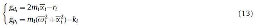
The two gains gdi and gpi allow the pole for the ith vibration mode to be allocated. In fact, choosing the pole position of the controlled system  as
as

and remembering the relationship between mass, damping and stiffness and the system eigenvalues
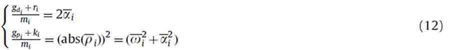
the gains can be obtained through the relationships
The two gains directly modify respectively the damping and the stiffness of each system mode. In any case stiffness variation (and as a consequence a natural frequency variation) requires very high control forces in common mechanical applications. These forces increase material stress and can lead to problems of structure health. Besides, in case of errors in natural frequencies estimation, high control forces can lead to unpredictable system behavior and, in some cases, to instability of the controlled system. For these reasons very often the choice gpi =0 is applied to modify only the system damping and leave its behavior unchanged at frequencies far from the natural ones.
2.2 Disturbance estimator
The decision to consider only the derivative contribution of modal components makes IMSC quite weak for disturbances acting in non-resonance region. Besides, modal control contribution is not very effective in canceling system response to external disturbance forces when their harmonic content is in the quasi-static or seismic region. To overcome this limit, a disturbance compensator can be adopted. Considering a disturbance force di . From the modal equation of motion (7), the generic ith equation can be considered

where the control force ƒci is the sum of the IMSC contribution (defined in Section 2.1) and the DE contribution.

The DE contribution is obtained multiplying the disturbance estimated in the previous integration step  by a gain Gi that will be defined in the following. To calculate the DE contribution, an auxiliary system, equal to the real one, can be introduced. The auxiliary system is forced by all the known forces applied to the real system (in this case only the control one)

where pi is the modal coordinate representing the component of system vibrations due only to the known forces. If, for every integration step, the initial condition of the real system is considered and the numerical model of the system proves to be equal to the real system, Eq. (16) can be subtracted from Eq. (14)

so that μi=qi-pi represents the contribution to system vibration due only to the unknown disturbances. Now the generic modal component di of disturbance forces can be obtained by solving the inverse dynamic of Eq. (17), since  are known. These forces, reconstructed and opposite in sign, can be applied to the system in order to compensate for the disturbance effects (Eq. (15)). From a theoretical point of view, a full feedback of the reconstructed force is able to completely cancel the vibration due to the disturbance. Anyway, due to the differences between the model and the real system (errors in the identification of system parameters, neglected modes, etc.), the estimated disturbance will not be equal to the real one. As a consequence, a full feedback could worsen the control performances. For this reason a gain Gi is introduced for each modal component of disturbance. This gain is a number between 0 and 1 and represents the ‘‘reliability’’ of the estimated disturbance. Gi=1 means a full feedback of the estimated disturbance, while Gi=0 means that no feedback is provided by the disturbance estimator.
2.3. Modal coordinates estimation
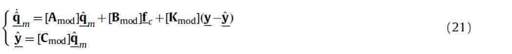
The considerations in the previous paragraph highlight the importance of the modal components estimation process. In fact it affects both the proposed control logics. The estimate can lead to significant problems in the later stages. A brief overview of modal components estimation is proposed. From Eq. (1), the state equation of the controlled system can be defined as
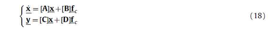
where x represents the state-space vector, y represents the measurements vector, [C] is the relationship between the measurements and the system coordinates, measurements and the system coordinates, [D] is identically null since in this application only velocity measurements are considered. Starting from the value of the y measurements, it is possible to obtain the system modal components using a state observer. The state observer is a model reproducing the internal dynamics of the mechanical system in which the estimated output y is constantly compared with the measurements y collected from the system. In this application based on the modal components, it is necessary to switch to modal coordinates by means of Eq. (4). In particular, considering the state-space representation, it is possible to define

where qm, representing the modal state-space vector, contains the modal velocities and displacements. Consequently
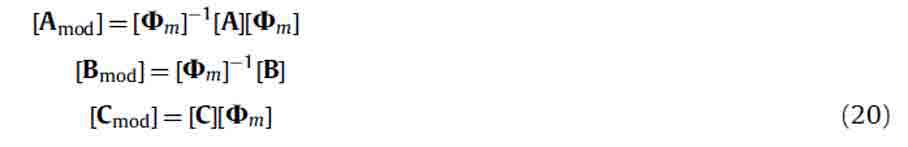
The estimated modal coordinates  can be obtained through the modal state observer defined by
The gain matrix [Kmod] of the state observer can be calculated using different methods. In this application, as for IMSC gains definition, the pole placement method is adopted. It is important to define a state observer with a dynamic faster than that of the auxiliary system by increasing the poles frequency. This allows us to obtain a correct estimate of system modal components up to a desired vibration frequency.
2.4. The control scheme
Combining the modal observer, the independent modal control and the disturbance estimator, a very powerful control logic can be obtained. A block diagram of the proposed control logic is shown in Fig. 1.
It is important to point out that both the control strategies can consider only a small number of system modes. In particular, remembering Eq. (8), the matrix ([Ф]T[∧F]T) must be invertible and this means that the number of modes considered (m) must be equal to the number of available actuators. At the same time, the auxiliary system and the observer can consider only a small number of system vibration modes in order to keep calculation time feasible for real- time application. In any case, these considerations are in accordance with the common applications in which the significant frequency range is well defined and only a small number of modes have a significant contribution on system dynamic.
Since the control scheme is developed on a reduced number of modes, its interaction with unconsidered modes must be considered. This topic is known in literature as spillover [9, 16]. This problem causes a worsening of control performances and can lead to system instability. It was demonstrated that, under the assumption of co-located sensors and actuators, spillover instability can be avoided [17], but in many applications (as for example the considered one) this assumption cannot be satisfied. Anyway, spillover problem is usually more critical when the system modes are not well separated (as for example on plates [18]) while beam-like structures typically have well separated natural frequencies.
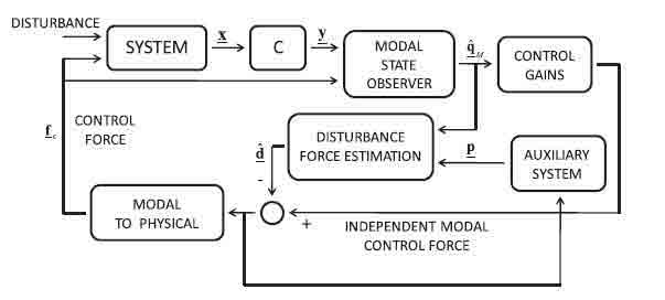
Fig. 1. Block diagram of the complete control logic
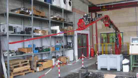
Fig. 2. The test rig
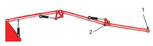
Fig. 3. Sensor position on the test rig
3. The etestrig and the numerical model
In order to validate the logic illustrated, a numerical/experimental campaign was carried out. The system considered is a flexible boom composed by a series of three segments connected by revolving joints and controlled by hydraulic actuators (Fig. 2).
For the numerical analysis, a nonlinear FEM model of the boom was used (see Ref. [19]). The model describes both the large system motion and small vibrations. The modal states estimation is performed using two velocity sensors, placed on the tip of the second and third segments (Fig. 3). During the experimental campaign, the same velocities were obtained through integration of accelerometric measurements.
The feedback control forces, the sum of the Independent Modal-Space Control and disturbance estimator, are applied to the system by means of the same actuators that perform the boom’s large motion. Since three actuators are available on the boom, the first three system modes were considered for control. Table 1 shows the natural frequencies and damping ratios associated with these modes for the boom configuration represented in Fig. 3.
The poles position both for the controlled system and the modal observer is given by imposing the frequency variation from the uncontrolled system and the desired damping ratio. The IMSC gains are chosen using the pole placement method. In this case, since the control target is the reduction of system vibration, the system damping has been increased to 10%, while the natural frequencies have not been modified. Also the observer gains are chosen with pole placement method. Since the modal observer requires a faster dynamic than the system one to return a correct mode estimation, its natural frequencies have been increased as reported in Table 2. In this way the observer is able to follow the system dynamics without relevant delays. Finally, Table 3 shows the disturbance estimator gains considered in numerical and experimental analysis. Lower gains are assumed for higher modes where the modal component estimation is less performant.
It is important to underline that the proposed control scheme is rigorous only for linear systems, where modal space can be defined. Anyway, for nonlinear systems, modal control approaches can still be used under certain assumptions. In particular, for the considered system, the nonlinearities are due to large rotations of the boom links. Under the assumption of small link rotation speed, the modal approach can still be considered for control, adopting a gain-scheduling approach [19].
4. Numerical and experimental results
The first numerical/experimental analysis was carried out with a fixed boom configuration (see the sketch in Fig. 3). This means that, apart from vibrations, the boom does not change its configuration and, for this reason, assuming small displacements its behavior can be considered linear. In order to evaluate the control performances a displacement is imposed on the first actuator, to simulate an external disturbance. The transfer function between the given displacement and the acceleration measured on the third segment tip in a defined configuration is evaluated with a sweep test in the [0– 7 Hz] frequency range. Figs. 4 and 5 show a numerical–experimental comparison. In particular Fig. 4 shows the numerical results considering only IMSC (on the left) and both control logics (on the right). Fig. 5 shows the same results obtained on the experimental test rig. A comparison between Figs. 4 and 5 shows very good agreement between numerical and
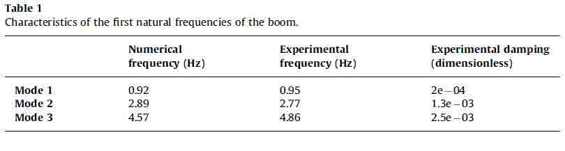
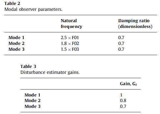
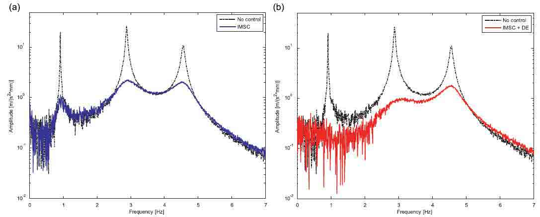
Fig. 4. Numerical results in the linear case: comparison between non-controlled system and IMSC (a) and comparison between non-controlled system and DE (b)
experimental data in both cases. It can be underlined that the disturbance estimator is able practically to cancel system vibrations, in particular at low frequencies (below 3 Hz).
It was mentioned earlier that the proposed control logic requires a good estimate of modal coordinates. The quality of this estimate depends on the validity of the dynamic model of the system. For this reason, an experimental analysis of the control performances varying system parameters was carried out. In particular the results were obtained by applying a mass of 10 kg to the boom tip (Fig. 6), while control and observer parameters were calculated on the original boom, without added masses (Tables 2 and 3).
Comparing the transfer function reported in Figs. 7 and 5, it can be seen that in this case the natural frequencies of the real system are very different from the expected ones (see in particular the second one). Anyway, both IMSC (Fig. 7a) and IMSC combined with DE (Fig. 7b) show good behavior demonstrating significant robustness even in the presence of high variation in the system modal parameters.
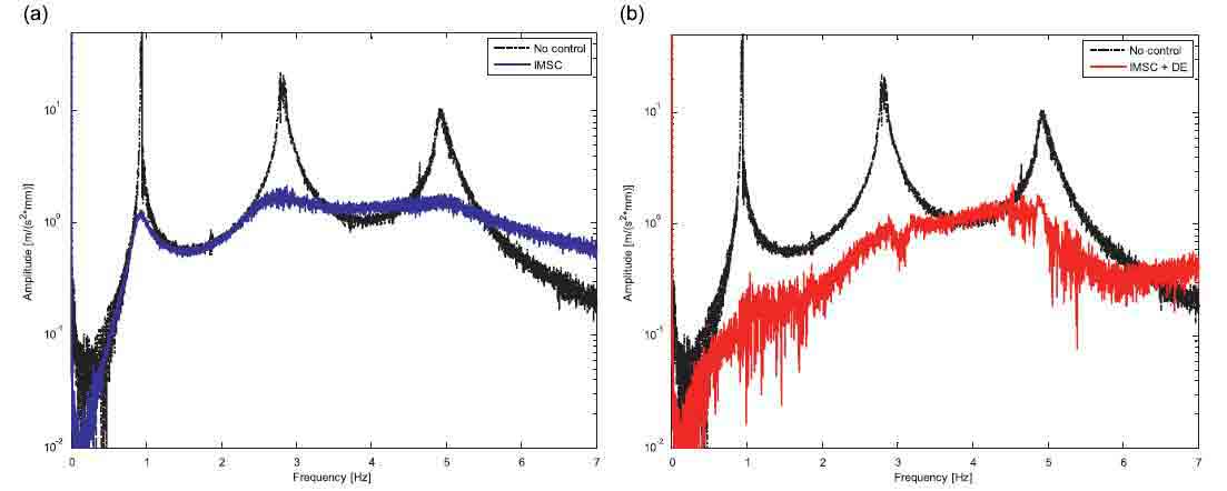
Fig. 5. Experimental results in the linear case: comparison between the uncontrolled system and IMSC (a) and comparison between the uncontrolled system and DE (b)
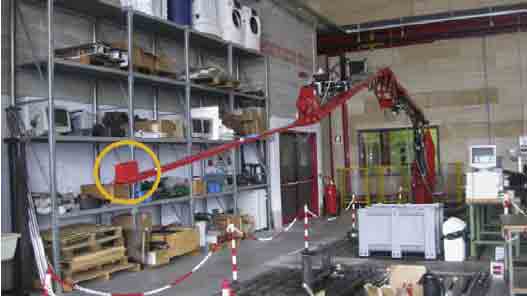
Fig. 6. Test rig with a 10 kg mass applied to the tip
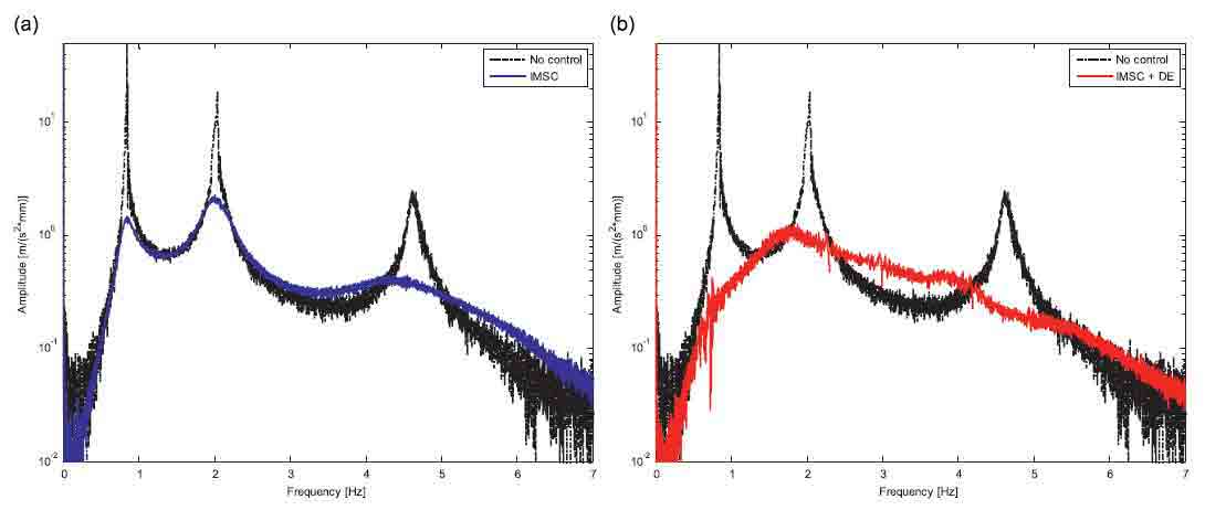
Fig. 7. Experimental robustness analysis: comparison between uncontrolled system and IMSC (a) and between uncontrolled system and DE (b)
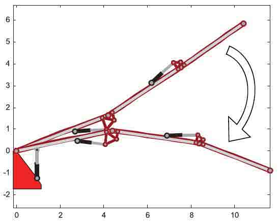
Fig. 8. Representation of the large motion performed by the system
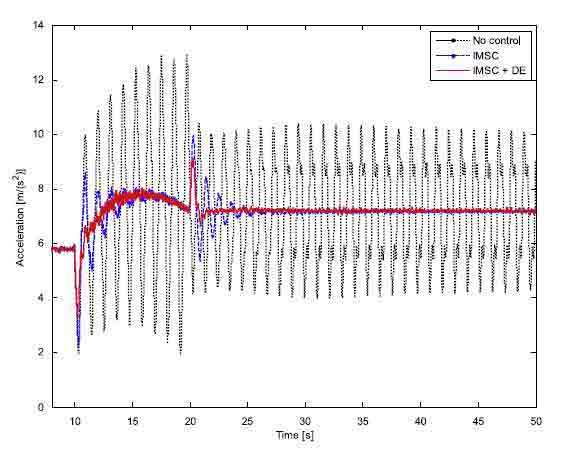
Fig. 9. Experimental results in the nonlinear case: comparison between uncontrolled system, IMSC and IMSC+DE
Finally the control performance during a large motion was analyzed. In this case gain-scheduling approach was applied to consider the variations of system parameters and gains during boom motion. Fig. 8 shows a sketch of the system’s large motion, while Fig. 9 shows the results using IMSC only and both IMSC and DE. It is important to point out that in this case the movement imposed by the actuators acts as an impulsive force on the system. Also in these conditions the effectiveness of the combined action of IMSC and DE can be seen. The proposed control logic is able to cancel system vibrations even during movement in about half a cycle, with significant improvement with respect to IMSC.